Digital Potentiometer - Isolated/Common Ground Query

Thread Starter

Cyclicz

Joined Apr 17, 2017
62
Hello!
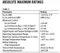
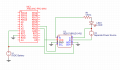
I'm currently building a circuit using an 8-pin DIP Digital Potentiometer (AD5171) and controlling it with an Arduino. I was wondering if these digital potentiometers have (in a general sense) an "Isolated ground". If I end up running my Arduino controlling an AD5171 on an isolated ground loop will it still work? I'm sure it will but there's always the possibility that it won't. If the ground is "Isolated" do I connect pin 6 of the AD5171 to the logic ground?
 

Attachments

DickCappels

Joined Aug 21, 2008
10,175
I don't have any experience with this chip but it looks like your circuit would work but (as you suspect) you need to make sure that all three connections to the "pot" are kept between GND and Vdd, otherwise something could be damaged on the chip.

To wit:
upload_2017-5-9_10-42-17.png
(Part of table removed for clarity)

That means that in your circuit VA should connected to ground.

By the way did you notice that this part is OTP (One Time Programmable)? Once you write a value to it you cannot change the value.
upload_2017-5-9_10-45-10.png

You might prefer the AD5227
 

Attachments

Sensacell

Joined Jun 19, 2012
3,447
No- bad idea.

The Pot "resistor" is not isolated, and must be operated strictly within it's specified voltage range.

If you are trying to dim an LED, there are many better ways.
 

Motanache

Joined Mar 2, 2015
540
The solution with IC is elegant.
As an idea I used something simpler - A photoreistor coupled with a light bulb or LED.

Edit: Typo corrected -dc
 
Last edited by a moderator:

Thread Starter

Cyclicz

Joined Apr 17, 2017
62
I don't have any experience with this chip but it looks like your circuit would work but (as you suspect) you need to make sure that all three connections to the "pot" are kept between GND and Vdd, otherwise something could be damaged on the chip.

To wit:
View attachment 126296
(Part of table removed for clarity)

That means that in your circuit VA should connected to ground.

By the way did you notice that this part is OTP (One Time Programmable)? Once you write a value to it you cannot change the value.
View attachment 126298

You might prefer the AD5227
Thank you for the helpful insight. I appreciate the pointer on OTP and I'll use your AD5227 reccomendation instead.

No- bad idea.

The Pot "resistor" is not isolated, and must be operated strictly within it's specified voltage range.

If you are trying to dim an LED, there are many better ways.
The solution with IC is elegant.
As an idea I used something simpler - A photoreistor coupled with a light bulb or LED.

Edit: Typo corrected -dc
And yes, this would be one of the absolute worst ways to dim an LED (and definitley not efficient), I had myself a chuckle. I had just used the LED as an example load.

I have no further questions.
Thanks again, everyone!
 
Top