 Facebook
 Google
 GitHub
 Linkedin
Hi,hi,
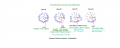
When on Position #1 , all the switch wipers are connected to Pos#1
Remember it is the switch wiper which is making the selection for each individual group
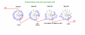
When the mode is on position 1,do all the contacts(circles)that have the upper 1 numbers are connected?
No, all the Pos#1 circles are not linked together
Even though the wiper is connected to position #1, unless there is a wire connected to pin #1 of that group, the wiper goes to no other part of the circuit, it is open circuit.
When the selector mode on position 2,do all the contacts that have the upper 2 numbers are connected?
No,
When the selector mode is on position 3,do all the contacts(circles)that have the upper 3 numbers are connected?
No,
When the selector mode on position 9,do all the contacts that have the upper 9 numbers are connected?etc...etc..etc...
No,
There is no need to attribute the question specifically to this scheme,
but to any scheme that uses this pattern of numbers with selector switch.
E
So,from your explanation,i understand that it is not possible to know,by the scheme, which contacts the selector switch,actually,come in contact on each position and i have to practically dismantle the dmm and check it.
Am i right?
")


