Digital multimeter scheme issue

Thread Starter

xchcui

Joined May 12, 2014
309
Hello.

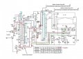
This is a circuit of a digital multimeter.In the circuit there are alot of small circles(connections),that demonstrate the connections between the circles as we turn the selector mode.Near each circle there are 2 numbers( _/ _),which are related to the tablet on the bottom.The first number shows the position of the selector refer to its function,but i couldn't figure out the meaning of the second number(_/?). So,how do the second numbers help to show the relationship between the circles?This might help me to understand how to use the numbers in order to follow the course of the circuit.
dmm scheme.jpg
 

ericgibbs

Joined Jan 29, 2010
21,439
hi X,
Do you have the multimeter on the bench for inspection.?

Usually the second number is the Switch Bank or wafer contact set.

E
 

Thread Starter

xchcui

Joined May 12, 2014
309
hi X,
Do you have the multimeter on the bench for inspection.?

Usually the second number is the Switch Bank or wafer contact set.

E
Thanks,E.
No,the multimeter is not on the bench right now.I checked that the 250mA fuse is okay
and i reassembled it back.The DC current measurement was not working with the 2mA and the 20mA functions.
Only the 200mADC and the 10ADC are working.So,i was trying to follow the current flow in the scheme,in order to see what components are involved,but i followed it until i reached to the circles and stopped,since i couldn't figure out how does the current is flowing beyond those circles.
Anybody know?
 

Thread Starter

xchcui

Joined May 12, 2014
309
Yes,thanks,it helps alot.
I have noticed that you highlighting with red color every circle that has the number 9(upper number),so the selector makes the connections among all
that circles,but i have noticed that there are three circles that also have the number 9,which you weren't highlight,so i wonder if they,also,powered
in that mode(2mA).
I marked them with circle and arrow in the attached photo.
I assume,that the one that is connected to the positive pole of the battery is
powered that circle in all the positions(besides position 6/OFF),so it doesn't
account,but what with the two other?do they,also,powered?
2)How these lower numbers,which you call them"Switch Bank or wafer contact set"contribute to understanding the connections among the circles,if at all?
dmm scheme 3.jpg
 

ericgibbs

Joined Jan 29, 2010
21,439
hi xc,
It is as I explained , the first number is the switch position number, the second number is the contact set group number.
I have expanded group #10 and group #11 to show what the draughtsman was trying to indicate by using just two numbers.

If the drawing showed all the switch wiring connections it would be more unreadable.
Eric
 

Attachments

Thread Starter

xchcui

Joined May 12, 2014
309
hi xc,
It is as I explained , the first number is the switch position number, the second number is the contact set group number.
I have expanded group #10 and group #11 to show what the draughtsman was trying to indicate by using just two numbers.

If the drawing showed all the switch wiring connections it would be more unreadable.
Eric
I understand.
What about the two connections,which i highlighted with red arrows before?
(group #4 and group #8)do they,also,being connected while the selector mode on 2mADC?Since i see that them both have the upper 9 number.
 

Thread Starter

xchcui

Joined May 12, 2014
309
Hi,Eric.
The marked up circuit that you attached and the expanded groups that you added,helps me very much to understand how to link each contact to another in every position of the selector mode.
But in order to be sure that i understood well how it works,it is very important for my understanding to know if the two contacts(circles)which i highlighted with red arrows(1-13/8,9/4)are ,also,connected when the selector function is 2mA(position 9).You marked with red color every circle that has the number 9(upper number),but you didn't mark the two circles that i mentioned,even though they have number 9.So,if they really are not connected when the position of the selector mode on 9(2mA)as the others you had marked,it will make me very confuse and i will understand that i didn't understand anything.
But if those two circles are,also,connected in the 9 selector position(2mA),
It will be a sign that i understand it well.
Eric,my main interest here is to understand the circuit much much more than
to repair the failed component.I know to read circuits,but this kind of circuit,which i need to match one contact to another by numbers is new for me,so i will very appreciate if you help me with that particular issue.
Thanks.
dmm scheme 3.jpg
 

ericgibbs

Joined Jan 29, 2010
21,439
hi xc,
OK, I will re-look at the circuit diagram, see what I can suggest.
At the moment I carrying out some final tests of a baby electric car electronics R/C control upgrade, hoping to give my great grand daughter a live demo on Friday this week.!
Give me about 24 hours.
What I would do is create a drawing showing all the switch groups and all of the possible 20 selected positions, then link the switch positions of interest.

E
 

Thread Starter

xchcui

Joined May 12, 2014
309
hi xc,
This explains the RED arrowed points on your circuit diagram.
E.
Hi,Eric.
I see at your respond,that there is no connection at pos 9 group 4
and at positions 1-17(while 9 pos is one of the 1-17)group 3.
So,that situation made me to wonder:why when i turn the selector mode to
position 9,all the contacts(circles)with upper 9 numbers are connected,besides
position 9/4 and 1-17/3 ?
When the selector mode is on position 9,Shouldn't all the contacts(circles)that have the upper 9 numbers be connected?
And when the selector mode on position 10,shouldn't all the contacts that have the upper 10 numbers be connected?etc...
 

ericgibbs

Joined Jan 29, 2010
21,439
hi xc,
Could you post a couple of photo's of the switch/pcb section.?
Confirm and post the Type and Model number of the DMM.

You report that the 2mA and 20mA settings on the DMM are not working.??
Have you tried the following diagnostic method.?

Connect say a 9v battery in series with a 1k resistor, connect the -Vbty to the DMM Com terminal and the end of the 1k to the DMM current input.
[ this will give a test current of approx 9mA]

Set the faulty DMM to 20mA.

Check with another DMM that the 9mA test current is actually 'flowing' into the faulty DMM current input terminal.
If not, it indicates an open current path in the meter.
Using the second DMM, with its -neg terminal connected to the DMM Com terminal, measure the 9v test voltages path thru the faulty DMM

If yes, [and the faulty DMM does not show the 9mA reading] it suggests that the voltage across the internal current sense resistor is not present at the 7106's input pin.
Use the second DMM to check the voltage path back from the 7106's input pin.

E
 

Thread Starter

xchcui

Joined May 12, 2014
309
hi xc,
Could you post a couple of photo's of the switch/pcb section.?
Confirm and post the Type and Model number of the DMM.

You report that the 2mA and 20mA settings on the DMM are not working.??
Have you tried the following diagnostic method.?

Connect say a 9v battery in series with a 1k resistor, connect the -Vbty to the DMM Com terminal and the end of the 1k to the DMM current input.
[ this will give a test current of approx 9mA]

Set the faulty DMM to 20mA.

Check with another DMM that the 9mA test current is actually 'flowing' into the faulty DMM current input terminal.
If not, it indicates an open current path in the meter.
Using the second DMM, with its -neg terminal connected to the DMM Com terminal, measure the 9v test voltages path thru the faulty DMM

If yes, [and the faulty DMM does not show the 9mA reading] it suggests that the voltage across the internal current sense resistor is not present at the 7106's input pin.
Use the second DMM to check the voltage path back from the 7106's input pin.

E
Hi Eric.
Thanks for your explanation,but as you can notice along all my posts and also from my thread title,my main interest is to understand the particularly part in the scheme(The selector mode connections),while it is less important to me how to find the failed component.And i have noticed that you didn't refer to my last question,which i asked several times.
May you regard to my particularly question which was:
Hi,Eric.
I see at your respond,that there is no connection at pos 9 group 4
and at positions 1-17(while 9 pos is one of the 1-17)group 3.
So,that situation made me to wonder:why when i turn the selector mode to
position 9,all the contacts(circles)with upper 9 numbers are connected,besides
position 9/4 and 1-17/3 ?
When the selector mode is on position 9,Shouldn't all the contacts(circles)that have the upper 9 numbers be connected?
And when the selector mode on position 10,shouldn't all the contacts that have the upper 10 numbers be connected?etc...
 
Last edited:

gdm_klog

Joined Feb 24, 2013
10
Yeah, Eric - why aren't you helping him fast enough ;);)
Hats off 2u re great-grandkids. I've only just got the grand ones.
 
Last edited:

ericgibbs

Joined Jan 29, 2010
21,439
Yeah, Eric - why aren't you helping him fast enough ;);)
Hats off 2u re great-grandkids. I've only just got the grand ones.
hi gdm,
I am working on the TS's problem, but is difficult without any photo's of the DMM, I hope he will post a photo.
E

OT:
I have 31 offspring in my gene pool, 2 children, 6 grand children, 19 great grand children and 4 great great grand children, so you can see how they keep me busy and poor.:rolleyes:

E
 
Last edited:

gdm_klog

Joined Feb 24, 2013
10
hi gdm,
I am working on the TS's problem, but is difficult without any photo's of the DMM, I hope he will post a photo.
E

OT:
I have 31 offspring in my gene pool, 2 children, 6 grand children, 19 great grand children and 4 great great grand children, so you can see how they keep me busy and poor.:rolleyes:

E
Blimey - must be the wet nights in your locale causing it LOL.
Forget upvotes on fora - the admiration from a child knocks them for six!

Geoff.
 

gdm_klog

Joined Feb 24, 2013
10
hi gdm,
I am working on the TS's problem, but is difficult without any photo's of the DMM, I hope he will post a photo.
E

OT:
I have 31 offspring in my gene pool, 2 children, 6 grand children, 19 great grand children and 4 great great grand children, so you can see how they keep me busy and poor.:rolleyes:

E
Blimey - must be the wet nights in your locale causing it LOL.
Forget upvotes on fora - the admiration from a child knocks them for six!

Geoff (sorry for drift)
 

Thread Starter

xchcui

Joined May 12, 2014
309
Hi Eric.

I wish you to live a long long life,so you will see all your offspring wedding.
And don't get me wrong,i didn't mean to urge you to answer my question,as gdm_klog hinted,i am trying to explain you,that i don't interest on repairing
the failed component,just to understand the specific selector mode connections(by the scheme and not by follow the dmm switch connections ,tracks etc).
I could dismantle the dmm again and take some photos,but it
is not the issue here.
I just would like to know refer to the scheme:
When the selector mode is on position 1,do all the contacts(circles)that have the upper 1 numbers are connected?
When the selector mode on position 2,do all the contacts that have the upper 2 numbers are connected?
When the selector mode is on position 3,do all the contacts(circles)that have the upper 3 numbers are connected?
When the selector mode on position 9,do all the contacts that have the upper 9 numbers are connected?etc...etc..etc...
There is no need to attribute the question specifically to this scheme,
but to any scheme that uses this pattern of numbers with selector switch.
Thanks.
 

ericgibbs

Joined Jan 29, 2010
21,439
hi,

When on Position #1 , all the switch wipers are connected to Pos#1
Remember it is the switch wiper which is making the selection for each individual group


When the mode is on position 1,do all the contacts(circles)that have the upper 1 numbers are connected?
No, all the Pos#1 circles are not linked together
Even though the wiper is connected to position #1, unless there is a wire connected to pin #1 of that group, the wiper goes to no other part of the circuit, it is open circuit.


When the selector mode on position 2,do all the contacts that have the upper 2 numbers are connected?
No,

When the selector mode is on position 3,do all the contacts(circles)that have the upper 3 numbers are connected?
No,

When the selector mode on position 9,do all the contacts that have the upper 9 numbers are connected?etc...etc..etc...
No,
There is no need to attribute the question specifically to this scheme,
but to any scheme that uses this pattern of numbers with selector switch.

E
 
Top