Facebook
 Google
 GitHub
 Linkedin
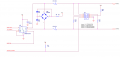
With this topic I would like to request feedback for a project I am busy with for some time now.
I am looking for feedback on the schematics as well ass the board layout/routing. I am no electronics engineer and this schematic is what I think should be working in "my theoretical world". However I would greatly appreciate if some of you experts would take a look.
Primary functions:
Thank you in advance.

I am looking for feedback on the schematics as well ass the board layout/routing. I am no electronics engineer and this schematic is what I think should be working in "my theoretical world". However I would greatly appreciate if some of you experts would take a look.
Primary functions:
- Switching 7 12V push button led lamps (build in the push button) (X2 X3 X4 X5 X18 X19 X20);
- Switching of 2 solenoid's (24VAC) - (X1 & X17);
- Switching of VAC lamps/outlet (230VAC) - (X13)
- Detection of 7 push buttons pressed (X6 X7 X8 X9 X14 X15 X16);
- Detection of 230VAC lamp switch on/off - (X12);
- (1 transformer -> 1 primary - 2 secondary )
- X11 = 16 VAC input from a transformer
- X10 = 24VAC input from a transformer
- RS485 circuit in general (1 resistor or jumpers with additional 2 resistors to ground en 5V?);
- Ground plane?
- 60 ohm resistor on the 24VAC to power the solenoid?
(solenoid characteristics: 370 mA inrush, 210mA holding, 50 HZ)
Thank you in advance.
Attachments
-
440.5 KB Views: 25
-
1.1 MB Views: 16
-
137 KB Views: 13