Digital controlled LM317 (DAC) with arduino

Thread Starter

mahmut_kelesoglu

Joined Aug 12, 2022
67
Hi,
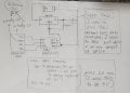
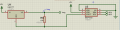
I need to control LM317 digitally with DAC. I connected DAC's VCC pin to Arduino's 5 V. SDA pin to A4, SCL pin to A5. Connected A0 and gnd pins to my circuit's gnd which I fed LM317. But, when I create real circuit and test it, I take 2.7 V to 3.3 V from LM317 output. I should take 1.25 to 6.25 V. when I check Arduino's gnd, I realized that it is not 0. ıt is -3 V. Arduino's 5V is actally +2V. which yields voltage different of 5 V. but, I have to connect DAC's gnd to my real circuit gnd which is 0 V. please help me. ı need to take 1.25 V- 6.25 V from output of the LM317. Circuit is attached.
 

Attachments

BobTPH

Joined Jun 5, 2013
8,813
Signals cannot pass between circuits without a common reference.

Is there a reason you cannot connect all the grounds together?
 

Thread Starter

mahmut_kelesoglu

Joined Aug 12, 2022
67
Signals cannot pass between circuits without a common reference.

Is there a reason you cannot connect all the grounds together?
ı need to power LM317 with 9V with 0 volt (gnd) reference. I have to connect gnd pin of dac to this 0 volt, not to arduino's gnd (-3V). I do not know the reason but it is necessary.
 

BobTPH

Joined Jun 5, 2013
8,813
Sorry, then your circuit cannot work. A common reference is necessary.

Also, can your DAC sink current? Because that is also necessary.
 

ci139

Joined Jul 11, 2016
1,898
I need to control LM317 digitally with DAC
if you add low pass ← it introduces latency + causes the output of the LM317 potentially to become unstable
if you do not add "S&H"/low-pass -- then you feed your control pin of the LM317 with signal containing switching artifacts ← which likely will make the LM317 output potentially unstable (even more when it's a LIVE/continuous DAC output)

? what is that you actually are trying to achieve
 

djsfantasi

Joined Apr 11, 2010
9,156
what can ı do for fix that "common reference" thing.
Connect the grounds together. The -3V is relative and based on a different reference point. Voltage is always between two points. The two points on the Arduino have no relation to the two points on the DAC - unless you connect the grounds together. Then all will be hunky dory (all right)
 

WBahn

Joined Mar 31, 2012
29,978
dac does not sink current. and what can ı do for fix that "common reference" thing.
What are the other ends of your 9 V and your 5 V supplies connected to? The schematic implies that they are BOTH connected to pin 2 of U5. If this isn't the case, what IS the case?
 

Thread Starter

mahmut_kelesoglu

Joined Aug 12, 2022
67
What are the other ends of your 9 V and your 5 V supplies connected to? The schematic implies that they are BOTH connected to pin 2 of U5. If this isn't the case, what IS the case?
ın my real circuit, U5 is DAC. Its vss and a0 pins are have to be connected to gnd (0 V) together.
9 V is my battery which fed LM317. It has gnd of 0 V. I have to connect dac's grounds to this 0 V.
The 5 V is set to 5 V for making simulation works as requested, but in real life, it connected to arduino's 5V pin which actually gives 2 V. (arduino has 5 V = 2-(-3). -3 is the gnd of arduino)
ı need to connect dac gnds to 0 volt, dac vdd to arduino's 5V which has 2V. then ı have a voltage difference of 2 V on DAC. but ı want it to be 5 volt max.
this IS the case.
ı need to stabilize my LM317 output btw 1.25 to 6.25 volts.
 

Thread Starter

mahmut_kelesoglu

Joined Aug 12, 2022
67
Connect the grounds together. The -3V is relative and based on a different reference point. Voltage is always between two points. The two points on the Arduino have no relation to the two points on the DAC - unless you connect the grounds together. Then all will be hunky dory (all right)
you are rigth. arduino have no relation on gnds, but it gives 2 volts to dac. not 5 v. because ı have voltage difference of 2-0=2 V on dac. if ı connect dac's gnd to arduinos gnd (-3 V), it will work well but ı must connect dac's gnd to actual gnd (0 V).
 

BobTPH

Joined Jun 5, 2013
8,813
Connect the grounds together. The -3V is relative and based on a different reference point. Voltage is always between two points. The two points on the Arduino have no relation to the two points on the DAC - unless you connect the grounds together. Then all will be hunky dory (all right)
He says he cannot do that, but does not know why.
 

djsfantasi

Joined Apr 11, 2010
9,156
you are rigth. arduino have no relation on gnds, but it gives 2 volts to dac. not 5 v. because ı have voltage difference of 2-0=2 V on dac. if ı connect dac's gnd to arduinos gnd (-3 V), it will work well but ı must connect dac's gnd to actual gnd (0 V).
Those “ground” measurement are meaningless, because they have no common reference point. Which would be created when you connect the DAC and Arduino ground points together.

Just to be clear, where are you placing your DMMs probes when you measure -3V? (By the way, to eliminate any misunderstanding, you should attach a pencil/pen drawing of how you’ve wired the DAC and Arduino)
 

crutschow

Joined Mar 14, 2008
34,283
The 5 V is set to 5 V for making simulation works as requested, but in real life, it connected to arduino's 5V pin which actually gives 2 V. (arduino has 5 V = 2-(-3). -3 is the gnd of arduino)
As you have been asked, several times, why is -3V the arduino ground?
That's a odd thing to do.
 

sagor

Joined Mar 10, 2019
903
Poster has been told repeatedly to tie all the grounds together, but still seems to resist this. No point trying to help him any further until he ties those grounds together, nothing will work properly.
 
Top