Digital clock on breadboard

Thread Starter

Daniel Marinov 7098

Joined Jan 9, 2025
6
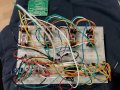
Hello, I want to ask because I have a problem with my project which is an LED clock. The problem is that now I have connected these four 7 segment displays to the circuit, but they should display 12:59. The problem is that it says 88:88 and I mean that the four displays have a common anode. Originally it was a four-bit display but it turned out to be defective and that's why I use separate ones. Can anyone help me what the problem is?1000201108.jpg1000198797.jpg1000201181.jpg
 

Attachments

MrChips

Joined Oct 2, 2009
34,630
If the seven-segment display is common anode, for the digit to show all 8s, the anodes must be at logic HIGH and the digits must be a logic LOW.

Check the voltage at the output pins P1.2 to P1.7.
Disconnect any one pin and see if the corresponding digit is turned off.
 

Thread Starter

Daniel Marinov 7098

Joined Jan 9, 2025
6
If the seven-segment display is common anode, for the digit to show all 8s, the anodes must be at logic HIGH and the digits must be a logic LOW.

Check the voltage at the output pins P1.2 to P1.7.
Disconnect any one pin and see if the corresponding digit is turned off.
Every single leg of the integrated circuit after I remove the cable on the display goes out. So when I remove some cable and a given segment goes out
 

panic mode

Joined Oct 10, 2011
4,871
did you buy it as a kit? if so then MCU should be already programmed (fingers crossed). if not it should contain instructions where to get code or compiled file to load it into MCU.

normally MCUs have bunch of GPIO (general purpose inputs and outputs). the GPIO need to be configured to be an input or output. normally, the default state is that GPIOs are working as inputs... but if they were inputs display would not light up. i would guess that configuration does exist in the MCU. maybe oscillator circuit is spotty and did not allow instruction pointer to reach part of the code where specific value would be displayed.

the 30pF for oscillator capacitors seems large, usually values are 18-22pF. and doing this on a breadboard instead of PCB adds another 10-15pF.

edit, just checked datasheet and for this chip 30pF is correct.

what tools/instruments you have at your disposal?
 

Thread Starter

Daniel Marinov 7098

Joined Jan 9, 2025
6
did you buy it as a kit? if so then MCU should be already programmed (fingers crossed). if not it should contain instructions where to get code or compiled file to load it into MCU.

normally MCUs have bunch of GPIO (general purpose inputs and outputs). the GPIO need to be configured to be an input or output. normally, the default state is that GPIOs are working as inputs... but if they were inputs display would not light up. i would guess that configuration does exist in the MCU. maybe oscillator circuit is spotty and did not allow instruction pointer to reach part of the code where specific value would be displayed.

the 30pF for oscillator capacitors seems large, usually values are 18-22pF. and doing this on a breadboard instead of PCB adds another 10-15pF.

edit, just checked datasheet and for this chip 30pF is correct.

what tools/instruments you have at your disposal?
Yes, it was bought as a kit, but I have no idea if it was programmed because it didn't work properly with the first display, then I discovered that it was defective and now I'm trying with four separate displays.
 
Top