digital circuit diagram

Thread Starter

fran1942

Joined Jul 26, 2010
58
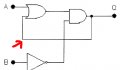
Hello, I have been asked to redraw this circuit using only one type of gate eg. 2 input OR.

But first of all, I cannot figure out how the wire works that I have labelled with the arrow.

How can it loop to the output while bypassing the AND symbol in between.
I am trying to write an equation for this circuit, but I can only come up with:
Q = A + ? . B

Can someone please help explain that to me.
Thanks kindly for any assistance.
 

Attachments

jegues

Joined Sep 13, 2010
733
Hello, I have been asked to redraw this circuit using only one type of gate eg. 2 input OR.

But first of all, I cannot figure out how the wire works that I have labelled with the arrow.

How can it loop to the output while bypassing the AND symbol in between.
Can someone please help explain that to me.

Thanks kindly for any assistance.
That wire simply feeds the output back and using it as an input.

You should be able to write a truth table with 3 inputs (8 possible states),

A, B, & Qprev

and one output,

Q.

From here you can use karnaugh maps or a number of other methods to simplify the circuit if need be.
 

Thread Starter

fran1942

Joined Jul 26, 2010
58
thanks for that.
I drew up a truth table, but am not sure if I understand properly.
I came up with:

A B Qprev Q
0 0 0 0
0 0 1 1
0 1 0 0
0 1 1 0
1 0 0 1
1 0 1 1
1 1 0 0
1 1 1 0


Would this be right. I am just having trouble understanding how you can feed the output into the input before you know the output value.

Thanks kindly.
 
Last edited:

jegues

Joined Sep 13, 2010
733
thanks for that.
I drew up a truth table, but am not sure if I understand properly.
I came up with:

A B Qprev Q
0 0 0 0
0 0 1 1
0 1 0 0
0 1 1 0
1 0 0 1
1 0 1 1
1 1 0 0
1 1 1 0


Would this be right. I am just having trouble understanding how you can feed the output into the input before you know the output value.

Thanks kindly.
You are missing one state, 0001.

Now write a boolean expression and determine the output for each case.

After doing so, you can further simplify the function if possible.
 

Thread Starter

fran1942

Joined Jul 26, 2010
58
sorry about this, but I still dont understand the concept.
Can I go back to a 2 input truth table without the feedback input:
So, how do you establish the third input (ie the feedback).
Thanks for your persistence.

A B Qprev
0 0 ?
0 0 ?
0 1 ?
0 1 ?
1 0 ?
1 0 ?
1 1 ?
1 1 ?
 

jegues

Joined Sep 13, 2010
733
sorry about this, but I still dont understand the concept.
Can I go back to a 2 input truth table without the feedback input:
So, how do you establish the third input (ie the feedback).
Thanks for your persistence.

A B Qprev
0 0 ?
0 0 ?
0 1 ?
0 1 ?
1 0 ?
1 0 ?
1 1 ?
1 1 ?
I understand your frustration.

You're hesitant to define the state of Qprev because it is based on the previous output, which we don't know, but don't worry about it.

Your truth table will covers all possible combination of inputs, so whatever the previous output was (even though you don't necessairly know what that is) your truth table will be able to obtain the correct output regardless.

Fill out a truth table for all possible combinations of the 3 inputs (a, b, Qprev) and from your boolean expression for Q, determine the output Q for each row in your truth table.
 

Thread Starter

fran1942

Joined Jul 26, 2010
58
thanks, it is getting throughly gradually.
Here is my new truth table with 3 inputs and 8 possible states.

Columns are A, B and QPrev. (QPrev is represented by 'C').

A B C QOut
0 0 0 0
0 0 1 1
0 1 0 0
0 1 1 0
1 0 0 1
1 0 1 1
1 1 0 0
1 1 1 0

These three lines give a Q output of 1:
0 0 1 1
1 0 0 1
1 0 1 1

So, my expression for these 4 is:
ACB + ACB +ACB

which I would then simplify.
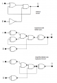
The original question I was asked was how to redraw this diagram using only one type of gate (hint use de Morgan theorem). Does anyone know how to do that ?
 
Last edited:

jegues

Joined Sep 13, 2010
733
thanks, it is getting throughly gradually.
Here is my new truth table with 3 inputs and 8 possible states.

Columns are A, B and QPrev. (QPrev is represented by 'C').

A B C QOut
0 0 0 0
0 0 1 1
0 1 0 0
0 1 1 0
1 0 0 1
1 0 1 1
1 1 0 0
1 1 1 0

These three lines give a Q output of 1:
0 0 1 1
1 0 0 1
1 0 1 1

So, my expression for these 4 is:
ACB + ACB +ACB

which I would then simplify.
Does these seem right ? Thanks.
I believe you've successfully indentified the 4 states that produce a HIGH output as well as the new expression for Q.

You should be able to simplify the expression now.
 

djsfantasi

Joined Apr 11, 2010
9,237
Hello, I have been asked to redraw this circuit using only one type of gate eg. 2 input OR.
Interesting analysis, and I hope the OP learned from it. But the OP's question seemed to me to be much simpler. Why not directly apply equivalent NAND gates to the circuit and implement it with only NAND gates (the requirement was to use only one type of gate; an OR gate was presented as an example but not a requirement, hence it would be easy to implement with either of the universal gates NAND or NOR)


Attachments

Top