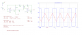
Difficulty Generating Triangle Wave with Wide Frequency Range

Papabravo

Joined Feb 24, 2006
22,082
I'm also not a fan; I think it is way over-prescribed. Sometimes it is the right part for the job, but this definitely ain't that time.

ak
I don't know what could be simpler and more linear than charging and discharging a capacitor from a current source. The wide frequency range could be readily accomplished with switched capacitors. I hope the TS gets the grade he expects.
 

MisterBill2

Joined Jan 23, 2018
27,530
I don't know what could be simpler and more linear than charging and discharging a capacitor from a current source. The wide frequency range could be readily accomplished with switched capacitors. I hope the TS gets the grade he expects.
Holding a constant current for that charge and discharge, and switching it on and off based on???
Admittedly the pain is in those little details, and they are so very easy to overlook. " Big Picture" sorts of folks are especially good at overlooking those details, and then the engineers get blamed for not solving all of those little show-stopper problems that nobody was willing to even admit existed.
 

AnalogKid

Joined Aug 1, 2013
12,136
BUT when the only tool that an individual has is a hammer, suddenly everything starts to look like a nail. Or something like that.
Seriously? You're saying that to me? Have you seen my tagline?

When I first became aware of these kinds of forums, I lurked for a while to get a feel for the levels of interactions, levels of expertise, etc. Back then I saw a major pattern in the responses to a wide variety of questions - almost every other response was either a 555 or a PIC. The little puppies were bent and squeezed into all manner of topics. Being the ak, I started pushing back on some of the recommendations - only where appropriate, of course. Hence, my tagline.

"I suppose it is tempting, if the only tool you have is a hammer, to treat everything as if it were a nail."

- Abraham Maslow, Professor of Psychology, Brandeis University
"The Psychology of Science: A Reconnaissance", 1966

ak
 

MisterBill2

Joined Jan 23, 2018
27,530
Seriously? You're saying that to me? Have you seen my tagline?

When I first became aware of these kinds of forums, I lurked for a while to get a feel for the levels of interactions, levels of expertise, etc. Back then I saw a major pattern in the responses to a wide variety of questions - almost every other response was either a 555 or a PIC. The little puppies were bent and squeezed into all manner of topics. Being the ak, I started pushing back on some of the recommendations - only where appropriate, of course. Hence, my tagline.

"I suppose it is tempting, if the only tool you have is a hammer, to treat everything as if it were a nail."
Besides that, the "Maslow" I am familiar with was actually "MASLOWSKI", an excelent professor in electronics at Lawrence Institute of Technology. That was before the school turned fink and became a University offering an MBA as the first advanced non-technical degree. And now, as a university, their tuition is 132 TIMES what I paid. And now it is a private university JUST LIKE ALL THE OTHERS, except with a better school of engineering. But the thing that made it special is long gone.

- Abraham Maslow, Professor of Psychology, Brandeis University
"The Psychology of Science: A Reconnaissance", 1966

ak
That comment was aimed at the use of a 555 timer for applications in which it was not the best choice. I tend to not name names, but certainly consider that applies in regard to circuits covering wide frequency spans.
 
Last edited:

crutschow

Joined Mar 14, 2008
38,512
Depending on the precision required.
Using a 50% duty cycle square wave and tapping off the timing cap with an op amp buffer will produce a waveform.
If by "precision" you mean how close it is to a true triangle-wave, than the exponential triangle-wave the 555 generates is only moderately close as compared to the true triangle the integrator circuit generates.
 

MrAl

Joined Jun 17, 2014
13,707
First of all, here's an image of the circuit in Pspice for TI
View attachment 308433

Now, I will introduce the equations involving this circuit:
\[ V_o = \frac{R_4}{R_3} \cdot V_{cc} \]
\[ f = \frac{R_3}{4R_4 \cdot (R_5 + R_{POT}) \cdot C_1} \]

Here is the procedure that I have followed in order to calculate the pasive components.
As I'm required to have an output of ±1V to ±5V, I decided to reduce the output to ±5V here:
\[ \frac{R_4}{R_3} = \frac{1}{3} \]

Using a potentiometer of 10kΩ:
\[ \begin{cases} f = 20 \text{ Hz} \text{ when } R_{POT} = 10 \text{ k$\Omega$} \\ f = 10 \text{ kHz} \text{ when } R_{POT} = 0 \text{ $\Omega$} \end{cases} \]

Using the equation for calculating the frequency:
\[ \begin{cases} 20 \text{ Hz} = \frac{3}{4 \cdot (R_5+10 \text{ k$\Omega$}) \cdot C_1}\\ 10 \text{ kHz} = \frac{3}{4 \cdot R_5 \cdot C_1} \end{cases} \]

Solving, I obtain \( C_1 \) and \( R_5 \):
\[ \begin{cases} C_1 = \frac{1497}{400 \cdot 10^6} = 3.7425 \text{ $\mu$F}\\ R_5 = \frac{10000}{499} = 20.0401 \text{ $\Omega$} \end{cases} \]

Simulating with LM311 is very slow for me for some reason, maybe It's a Pspice limitation. Using UA741 for both the Schmitt trigger and integrator, I get correct results for 20Hz, but an awfull mess for 10kHz.
Here are screenshots of simulations for both frequencies using LM311 as Schmitt trigger and TL082 as integrator. I don't understand why I'm getting this.
View attachment 308435

View attachment 308436


Note: R2 is a very high resistor to simulate that strob isn't connected to anything.
Here is a typical triangle wave generator circuit.
Since this works you probably have to adjust the LM311 circuit part. Maybe the component values or something.
You should keep the LM311 though as that is allowed for your design and will probably get you up higher in frequency.
 

Attachments

Thread Starter

lucumon

Joined Nov 25, 2023
10
My apologies for the delayed response. I didn't anticipate receiving so much help—thanks to everyone! I've been experimenting with many of your suggestions, and I stumbled upon a circuit in a book that's a slight variation of the one I was using.

1701373588095.png

The only problem I'm having with it is that I'm not able to achieve 10kHz, only 3kHz. Here's my circuit and simulation results:
1701373790487.png
1701373813238.png

I found out that increasing R4 and R5, the frequency goes up, but I can't understand why.

I attempted to use the LM311 for the Schmitt trigger in the same circuit. However, I encountered a voltage drop due to the pull-up resistor in COL_OUT once again. Unfortunately, I'm unable to utilize Schottky diodes, rendering the solution suggested in #16 impractical for me, despite its cleverness.

Cheers.
 

crutschow

Joined Mar 14, 2008
38,512
attempted to use the LM311 for the Schmitt trigger in the same circuit. However, I encountered a voltage drop due to the pull-up resistor in COL_OUT once again. Unfortunately, I'm unable to utilize Schottky diodes, rendering the solution suggested in #16 impractical for me, despite its cleverness.
You could use a standard silicon junction diode, but there would be slightly more mismatch between the high and low.
 

Thread Starter

lucumon

Joined Nov 25, 2023
10
One update on the last circuit I posted. Shorting R7 makes it work as expected, with a very good accuracy. This doesn't make any sense to me as I've used the following equations for calculating C1 and R7:

\[ \begin{cases} R_7 = \frac{Vcc}{2 \cdot Vcc \cdot \frac{R_3}{R_2+R_3} \cdot C_1} \cdot \frac{1}{2 \cdot 1 \text{ kHz}} \\ 100 \text{ k$\Omega$} + R_7 = \frac{Vcc}{2 \cdot Vcc \cdot \frac{R_3}{R_2+R_3} \cdot C_1} \cdot \frac{1}{2 \cdot 20 \text{ Hz}} \end{cases} \Longrightarrow \begin{cases} C_1 = 374.25 \text{ nF} \\ R_7 = 200.400 \, \Omega \end{cases} \]

Could someone please clarify why this circuit is having this particular behavior? Is it possible that the equations I used are incorrect?
 

MrAl

Joined Jun 17, 2014
13,707
One update on the last circuit I posted. Shorting R7 makes it work as expected, with a very good accuracy. This doesn't make any sense to me as I've used the following equations for calculating C1 and R7:

\[ \begin{cases} R_7 = \frac{Vcc}{2 \cdot Vcc \cdot \frac{R_3}{R_2+R_3} \cdot C_1} \cdot \frac{1}{2 \cdot 1 \text{ kHz}} \\ 100 \text{ k$\Omega$} + R_7 = \frac{Vcc}{2 \cdot Vcc \cdot \frac{R_3}{R_2+R_3} \cdot C_1} \cdot \frac{1}{2 \cdot 20 \text{ Hz}} \end{cases} \Longrightarrow \begin{cases} C_1 = 374.25 \text{ nF} \\ R_7 = 200.400 \, \Omega \end{cases} \]

Could someone please clarify why this circuit is having this particular behavior? Is it possible that the equations I used are incorrect?
Hello,

What frequency are you trying to get here?

Also, something does not look right.
Your previous post shows a ramp 'up' time of about 0.205ms, but a simple calculation shows a much longer time.
The voltage driving the 100k resistor is 15v, so with +15v the current into that op amp is:
15/100000=150ua
and that will be constant.
Now using the relationship:
dv/dt=i/C
and solving for dt we get:
dv=i*dt/C
dt=dv*C/i
and we are looking for a ramp of dv=10v with i=150e-6 and C=374.25nf, and so we get:
dt=24.95ms
This is much longer than your plot shows of about 0.2ms.
Is that plot you show correct because it does not seem like it is?
 

Thread Starter

lucumon

Joined Nov 25, 2023
10
Hello,

What frequency are you trying to get here?

Also, something does not look right.
Your previous post shows a ramp 'up' time of about 0.205ms, but a simple calculation shows a much longer time.
The voltage driving the 100k resistor is 15v, so with +15v the current into that op amp is:
15/100000=150ua
and that will be constant.
Now using the relationship:
dv/dt=i/C
and solving for dt we get:
dv=i*dt/C
dt=dv*C/i
and we are looking for a ramp of dv=10v with i=150e-6 and C=374.25nf, and so we get:
dt=24.95ms
This is much longer than your plot shows of about 0.2ms.
Is that plot you show correct because it does not seem like it is?

I'm aiming for a frequency range between 20Hz and 10kHz.

Your calculated pulse time corresponds to the potentiometer set at 100% (SET = 1), aligning with the lower limit of the frequency range, which seems accurate. However, in the simulation I shared, the potentiometer is set at 0%, which theoretically should produce a frequency of 10kHz.

Regarding my prior mention of shorting on R7, that was an error on my part. Although Pspice registered a frequency of 10kHz, the actual signal maintained a frequency of 2.45kHz. Maybe Pspice was measuring the frequency of some underlying noise rather than the intended signal.

Cheers.
 

MrAl

Joined Jun 17, 2014
13,707
I'm aiming for a frequency range between 20Hz and 10kHz.

Your calculated pulse time corresponds to the potentiometer set at 100% (SET = 1), aligning with the lower limit of the frequency range, which seems accurate. However, in the simulation I shared, the potentiometer is set at 0%, which theoretically should produce a frequency of 10kHz.

Regarding my prior mention of shorting on R7, that was an error on my part. Although Pspice registered a frequency of 10kHz, the actual signal maintained a frequency of 2.45kHz. Maybe Pspice was measuring the frequency of some underlying noise rather than the intended signal.

Cheers.
Hi,

Ok that makes more sense now.
However, I do not think you can set the pot at 0 percent to make that 100k pot zero Ohms. That's because then you are left with just the 200.4 Ohm resistor. Is that what you are doing for the highest frequency?
If you only have 200.4 Ohms there then the current into the following op amp circuit would be:
i=15/200.4=74.85ma
which is probably too high for the op amp.
Remember that for the circuit to work, the current through the capacitor has to be the same as the input current through the input resistor, and that means the output current from the op amp has to be about 75ma also, and I do not think that op amp can do that high of a current. You could check that though.
If that's the case, you will have to lower the value of the capacitor to get to the higher frequency.

Now if the maximum output of the op amp was 20ma, can you calculate the minimum value of the potentiometer?
That will help to determine the maximum size of the capacitor.
[LATER]
I just checked the data sheet, it says that the max current on the output would be closer to 15ma when the op amp swings negative. That means you should design for less than that instead of 20ma. The maximum positive output current is a little more but it has to work when the output goes negative too so that 15ma looks like the max.
Another point is that the outputs will not likely go all the way up to plus and minus 15 volts either. There's always some drop in the internal transistors. A better design target point might be 13v or something (check data sheet).
 
Last edited:
Top