differential measurement of large swing

Ron H

Joined Apr 14, 2005
7,063
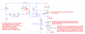
If you can't figure out how to make the drain common, here is a circuit that works in simulation. It limits the p-p ADC input to less than +5V, and the voltage you are trying to measure is relative to GND, i.e., if Vds=0.5V, then your ADC input will be 0.5V.
 

Attachments

Ron H

Joined Apr 14, 2005
7,063
M121212, I saw you looking at it.:D 
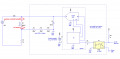
What do you think? Be aware that LTspice had trouble completing the sim with models of available op amps, but ran well when I used the universal op amp model. I am confident that hardware will run just fine.
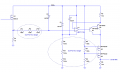
Of course, I was wrong once before.;)
 

Thread Starter

m121212

Joined Jul 24, 2011
96
Thanks for thinking about this for me!

I need some more time to understand what is going on in your design. Perhaps you could give me a brief explanation of how it works?

One thing I was not entirely honest about was the 500V - this could be somewhat variable. It's actually more like 300 +or- 50, but switching and inductive load could cause a surge up to 500.

I think this doesn't matter to U1 because D1 and D2 will still clamp to the correct voltages. I have to think about what it means for the remainder of the circuit.

Funny thing - I have the same issue with LTSpice convergence on real op amp models. Usually my assumptions that it'll just work are incorrect however :(
 

Ron H

Joined Apr 14, 2005
7,063
Hopefully the annotated schematic (attached) will explain how it works to your satisfaction. If not, come back with questions.

Note that the PNPs and MOSFETs are high voltage devices. If you replace them with other parts, look carefully at the specs first.

EDIT: I just realized that I could get rid of 3 resistors. See the attachment.
 

Attachments

Last edited:

Thread Starter

m121212

Joined Jul 24, 2011
96
Well, it took me six months to finally sit down and try this out. Ron, I am now realizing there is one major catch that affects the design you suggested: I don't have access to the system ground. That is, I have no place to connect the ground terminals of R5 and R8.

Going back through the thread, I realized that I never specified this. So sorry! This is a high side switch; A black box with one port (one terminal pair).

I will try to think of a way to salvage this design, but if anyone has a good recommendation, please do suggest it!
 

Thread Starter

m121212

Joined Jul 24, 2011
96
Now that I think about it, my Fluke digital voltmeter pretty much does what I'm trying to do. Does anyone know what the frontend of one of those looks like?
 

Ron H

Joined Apr 14, 2005
7,063
Now that I think about it, my Fluke digital voltmeter pretty much does what I'm trying to do. Does anyone know what the frontend of one of those looks like?
If you're talking about a multimeter, the entire Fluke is floating, from input to output.
 

Thread Starter

m121212

Joined Jul 24, 2011
96
Basically DC.

There are two main reasons I need to do this. First, I need to be able to track the on-state dissipation in the FETs. I do this with the on-state drop and the current (hall sensed).

Second, I need to check the health of the FETs as a kind of safety feature. If the voltage drop (and dissipation) goes above some max threshold, perhaps because a FET is dying, I want to disallow switching and indicate service is needed.
 

Ron H

Joined Apr 14, 2005
7,063
I would use floating ± power supplies, and power an op amp (if needed) and an A/D using these supplies. Protect the op amp or A/D with a resistor/zener clamp, as discussed previously. Use +500V as the local ground reference. Send the digital data to your global ground-referenced circuit through an optocoupler (assuming serial data), or multiple optocouplers, if you have to send parallel data and clock.
 

Thread Starter

m121212

Joined Jul 24, 2011
96
Well, I've spent a long time [ does anyone even remember this thread? :) ] looking for alternate solutions, but haven't found anything promising.

There are two problems with Ron's recommendation, but maybe there are easy fixes for them.

First, the zener clamp. If the switch is off, no current is supposed to flow through it. The zener clamp will however cause leakage around the switch. The best zener I've found needs 50 uA to hit the zener voltage. That's pretty good for a zener, but a lot of leakage for a switch.

Second, the optocoupler. Is there an app note somewhere that has a good circuit for how to digitize the voltage? I'm a bit concerned that the A to D to A will be slow.

thanks!
m121212
 

Ron H

Joined Apr 14, 2005
7,063
Well, I've spent a long time [ does anyone even remember this thread? :) ] looking for alternate solutions, but haven't found anything promising.

There are two problems with Ron's recommendation, but maybe there are easy fixes for them.

First, the zener clamp. If the switch is off, no current is supposed to flow through it. The zener clamp will however cause leakage around the switch. The best zener I've found needs 50 uA to hit the zener voltage. That's pretty good for a zener, but a lot of leakage for a switch.

Second, the optocoupler. Is there an app note somewhere that has a good circuit for how to digitize the voltage? I'm a bit concerned that the A to D to A will be slow.

thanks!
m121212
Are you implying that you are measuring MOSFET current in the load? If so, why not measure it between source and load?
And refresh my memory. Why do you need an optocoupler?
 

Thread Starter

m121212

Joined Jul 24, 2011
96
I'm trying to measure the voltage drop across RDS_on, when the switch is conducting.

The switch is a high side switch, and I only have access to the switch terminals. The ground for the power supply driving current through the switch is inaccessible.

When the switch is open, the potential across it is large, making it hard to do a simple diffamp measurement.

You recommended an optocoupler to act as an interface between the high potential of the switch and the low potential of the remainder of the system (ADC, microcontroller, etc).

I'm actually looking at "isolation amplifiers" from Avago now. They might simplify matters.

Still not sure about the zener leakage though.
 

Ron H

Joined Apr 14, 2005
7,063
Here is my best shot at this point in the discussion. Take it with a grain of salt, because I have never attempted anything like this.
I am, however, an old retired analog EE with a lot of experience.:rolleyes:

EDIT: The second option, with the resistors on the drain side, is probably better. Or maybe it doesn't matter.
 

Attachments

Last edited:

Thread Starter

m121212

Joined Jul 24, 2011
96
Not sure I understand.

The 1n751 needs 70 mA to regulate.

If M1 is closed, and has a few volts drop across it, (lets say 3V), that appears at the input of the ADC.

If M1 is open, the 500V appears across the three 100K resistors and the zener. Certainly the zener is choked off and can't regulate? 500V/300K = 1.6 mA?

Would it be possible to have the opto-iso come before the micro/ADC? The way I've been thinking about it, I would translate the voltage measurement down to the ADC level. The micro probably has five pins for programming, and a few more for peripherals, and I wouldn't want to have to opto-iso each and every one of those lines.
 

Ron H

Joined Apr 14, 2005
7,063
1N751 is spec'ed at 20mA, not 70mA.
5.1V zeners have a very sharp knee. In simulation, it is 4.9V @ 1.6mA. I don't have time to actually test one, but from my experience, that seems reasonable.
Ordinary optocouplers are neither linear nor predictable, in terms of transfer gain.
Linear optos are available, but, of the few that I have looked at, their transfer gain is apparently stable, but variable from unit to unit.
You might be able to use an isolation amplifier. I have no experience with them.
 

Thread Starter

m121212

Joined Jul 24, 2011
96
Ok. Leaking 1 mA might not sound like a lot, but it is in this application. I'd like to try get this under 10 uA.

The only solution I can think of is to measure across a large divider instead of a a zener. The disadvantage of this approach is that the resolution of the ADC will span the full 500V. So if it's a 12 bit ADC, the voltage resolution will be 500/(2^12) = 0.122V, which is quite coarse if the voltage drop across RDS_on is a max of about 3V.
 

Ron H

Joined Apr 14, 2005
7,063
Ok. Leaking 1 mA might not sound like a lot, but it is in this application. I'd like to try get this under 10 uA.

The only solution I can think of is to measure across a large divider instead of a a zener. The disadvantage of this approach is that the resolution of the ADC will span the full 500V. So if it's a 12 bit ADC, the voltage resolution will be 500/(2^12) = 0.122V, which is quite coarse if the voltage drop across RDS_on is a max of about 3V.
Where is the leakage? The zener current flows into the load. If you want to measure OFF current, don't do it in the load. Do it in the MOSFET, as I indicated in my schematic.
 
Top