Differential Amplifier circuit

Jony130

Joined Feb 17, 2009
5,488
Sorry, but what you mean by AD? Is it Advice???
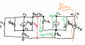
Sorry I forgot that in english we use Re. 1 - reference to the first question.
And what is that Vd that you're referring to?
Vd = Vb1 - Vbe2 = differential voltage
What means pedantic calcs?
pedantic - paying too much attention to small unimportant details
I think I have found a small difference between IC3 and IC4. In fact I_RC3 = IC3 + IB3 and IC4 might be different because of that... I probably assumed, wrongly, that IB3 = 0A
Well
I_Rc3 = Ic3 + Ib3 + Ib4
 

Thread Starter

PsySc0rpi0n

Joined Mar 4, 2014
1,763
Well
I_Rc3 = Ic3 + Ib3 + Ib4
Ah yes, you're absolutely correct, of course!

So, what would you suggest to simplify things regarding to the Q3 and Q4 Q-points? To consider both IB3 and IB4 as so low that can be neglected??? Or what should I neglect or consider to make those 2 transistor's Q-points the same?
 

Thread Starter

PsySc0rpi0n

Joined Mar 4, 2014
1,763
Ok, I think I have this correct... LTSpice confirms my calcs!

IC3 differs by around 20 μA from IC4 which I think can be neglected! The Q-point of Q3 and Q4 can't be the same because we have different impedances on both Q3 and Q4 collectors. So, current is roughly the same but not VCE. So I think I'm quite happy with the results, I guess. Please let me know otherwise!
 

Thread Starter

PsySc0rpi0n

Joined Mar 4, 2014
1,763
Now I need to do the Adm and Acm for this circuit!

I'm not sure how to do it because in classes we did a similar one but the mirrored current source has no emitter resistors.

I think our teacher only did the model stuff to this current source and not to the whole circuit. I'm not sure if it is this that is supposed to do, so I would appreciate a starting push!
 

Thread Starter

PsySc0rpi0n

Joined Mar 4, 2014
1,763
Ok, guys... I'm stuck again...

Considering this:
hfe = 255
RE3 = RE4 = 200 Ω
RC3 = 2 kΩ
hie = 3 kΩ

I have drew the equivalent hybrid model for the mirrored current source, have split it into two parts, and already solved the input impedance for the left part (Ry, marked in red) that returned me about 1.05kΩ, but now I'm struggling to solve for the output impedance (not input, as I have typed before) for the right side of the mirrored current source!

I'm trying to start by writing IB in terms of Ix but I'm not sure about this.

I'm considering the following:

IB and Ix are flowing out of the GND node while IE is flowing into that same node. So, can I write the following:

IE = IB + Ix??? But I think this leads me nowhere because:

IB = IE - Ix <=> IB = (hfe + 1)*IB + Ix <=> 1 = (hfe + 1) + Ix... ???

Then I tried to go for the current divider in the parallel of ( (Ry + hie4) || RE4 ) using the current Ix but also here I'm not sure if the current flowing through Ry is the same as the current flowing through hie4 but if this is correct:

IB =( RE4 / ( (Ry + hie) || RE4 ) ) * Ix

Ix = ( ( (Ry + hie) || RE4 ) / RE4 ) * IB

If Ix is correct, I'm trying now to sort out for Vx but I just don't know where to take Vx out from!!!
 

Attachments

Last edited:

Jony130

Joined Feb 17, 2009
5,488
First are you sure that Ry is 1.05kΩ. From what I see Ry = (RE3 + hie3/(hfe + 1)) || Rc3 = (200Ω+ 11.7Ω)||2kΩ = 191.4Ω.
Also notice that Ry is in series with hie4 and do not forget about KVL.
 

Thread Starter

PsySc0rpi0n

Joined Mar 4, 2014
1,763
Ok, I've attached my work for the left part of the mirrored current source.

Can you check it please?

Note:

In the attached picture, I called Ry as Rx...
 

Attachments

Thread Starter

PsySc0rpi0n

Joined Mar 4, 2014
1,763
Ok, probably my symbolic calcs are not correct, despite the fact that I also typed wrongly the RE3 of the denominator of the equation in the above attached picture. I should have typed 0.2 and I typed 2.2 but even if I redo the calcs I get 2 kΩ.

Also, I messed up in the today's first post. I mean I need to know the output impedance of the right side of the current mirror, not the input impedance!
So, to make things clear I need the input impedance of the left side of the mirrored current source and the output impedance of the right side of the mirrored current source!
 
Last edited:

Thread Starter

PsySc0rpi0n

Joined Mar 4, 2014
1,763
Oh, yes... I have used RE3 as 2.2 kΩ in my calcs which is wrong... If I use 200 Ω, Ry is in fact ≅192 Ω.

Thank God, at least this Ry is correct! Let me inspect your tip @Jony130, for the other part od the circuit.
 

Thread Starter

PsySc0rpi0n

Joined Mar 4, 2014
1,763
Ok, I think I made a mistake in the post where I told about Ix current.

Correcting my previous expression:
IB = ( Ix * RE4) / ( hie4 + Ry + RE4)
Ix = ( (hie+Ry+RE4) / RE4) * IB.

Now I'm trying for Vx.

Edited;
Is there any chance that Vx is:
CodeCogsEqn.gif
 
Last edited:

Bordodynov

Joined May 20, 2015
3,180
PsySc0rpi0n #2
....But now, as I don't know the transistor gain, I'm not sure if I'm supposed to assume a gain of 100 or 200....
I apologize. Before you take the final decision, I will come back a little bit ago. This will be useful in the future. That calculation Beta_DC. BF>=<Beta_DC>=<Beta_AC !!!DC1.png
 

Attachments

Thread Starter

PsySc0rpi0n

Joined Mar 4, 2014
1,763
Morning @Bordodynov ...

I'm using LTSpice's 2N2222A hfe which is 255 which pretty much matches the "bf" you have in the circuit! But the most important is to check my equation or how can I do it! @Jony130 suggested me the KVL but I'm not yet getting there!
 

Thread Starter

PsySc0rpi0n

Joined Mar 4, 2014
1,763
I have been using the value of 255 for my calcs and the results have been consistent so far. I just wanted to know if my equations for Ix and Vx are fine or not. I'll handle simulations with LTSpice later!
 

Bordodynov

Joined May 20, 2015
3,180
PsySc0rpi0n.
I did some calculations. In particular, I made a calculation of the dynamic resistance of the current mirror. And I brought an equivalent circuit of the current mirror. This manual calculation. I'm too lazy to do it manually. You have to do it yourself. The calculations substitute dynamic resistance of the current mirror instead of the current driving resistor Ree. So far, it turned out not very accurate, but it is adequate for practice (13%).
 

Attachments

Top