Differential +-10V ADC and potentiometer

Thread Starter

Primoz3

Joined Dec 7, 2016
9
Hello!

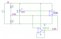
I have an ADC module from B&R X20AI4632 (link to datasheet with schematics), which requires a bipolar +-10V differential voltage input.
My sensor is a 10kOhm precision potentiometer (datasheet) which will serve as a position sensor and I have a 24VDC power supply available for voltage supply.

What would be the optimal solution for wiring the potentiometer? I have the following idea (see figure) - am I going in the right direction?
Are there any standard solutions to retain a clean output signal?

Also, I will only be able to use only 160deg of the full 340deg potentiometer range. This means (in order not to waste ADC resolution) I would have to amplify my bipolar UADC voltage by a factor of about 2. Is it possible to do this without an additional voltage supply in addition to the existing 24VDC?

Thank you - I'll appreciate any input!

poti.png
 

AlbertHall

Joined Jun 4, 2014
12,625
This circuit will give, with the fraction of the rotation you state, ±5.6V so an amplifier with a gain of just under two will give you the ±10V you want. You will need ensure that the ADC input range allows the inputs to reach 22V and care will be needed in the choice of amplifier as the output will be getting close to available supply voltage.
 

ericgibbs

Joined Jan 29, 2010
21,439
hi P3,
You could consider a Virtual ground to split the 24v into +/-12V, us a INA output to give the ADC input.
The 350R's represent your post and fixed resistors.

Note: the test signal is only +/-10mV
E
EDIT:
Image 2 is with a +/-100mV signal, giving a +/-10Vout
 

Attachments

Last edited:

Thread Starter

Primoz3

Joined Dec 7, 2016
9
Thank you for your inputs!
I have done some more research based on your suggestions and came up with the following schematics.
(I am a newbie in electronics design so I just found pieces of already designed circuits and put them together - there might be some adjustments needed. I will appreciate any input.)

My schematics: (R3 is my precision potentiometer sensor)
0.PNG
My thought process:
  1. Regulate the 24VDC switching supply with an LM317 to get a consistent 22V voltage.
    (I can set the voltage output with the R2 potentiometer)
    based on: 1.PNG
  2. Create a virtual ground using a TLE2426 rail splitter (8 pin version with noise reduction)
    based on: 2.png
  3. Amplify the signal with an INA121 (G=1+5kOhm/Rg)
    (set desired gain with the R4 potientiometer)
My questions/doubts:
  1. Is the INA121 a suitable opamp for this application? Might there be a better alternative for the gain I need? (just under G=2)
  2. The TLE2426 can handle 20-40 mA of current, but I figure it should be fine, right? My load is the 10k Potentiometer on let's say 24V, which gives only 2.4mA.
  3. I am quite tight with voltage drops, but I figure I should just get away with it:
    The dropout voltage of the LM317 will cost me about 1.5-2V:
    3.PNG
    The output voltage swing of the INA121 should also stay under 1V and allow me to set a +-10V differential signal to ADC:
    4.PNG
I know it's a lot to ask but I will really appreciate if someone with expirience could quickly check if my design and thought process is right.
I also linked all datasheets on the component names to provide necessary information.
BTW: My ADC allows up to +-30V on the pins so over voltage should not be a problem.

Thanks!
 

ericgibbs

Joined Jan 29, 2010
21,439
hi P3,
Basically the circuit looks OK, not sure what you mean by ADC+ and ADC-.?
The R2 , R3 and R4 variables maybe a little too coarse for fine adjustment, you may need to add a lower value pot in series with a fixed resistor.

E
 

Thread Starter

Primoz3

Joined Dec 7, 2016
9
hi P3,
Basically the circuit looks OK, not sure what you mean by ADC+ and ADC-.?
The R2 , R3 and R4 variables maybe a little too coarse for fine adjustment, you may need to add a lower value pot in series with a fixed resistor.

E
Hi ericgibbs,
thanks for the fast reply.
The ADC+ and ADC- are the signal pins I connect to the differential +-10V ADC I am using. (I am sorry if the symbols I used are not according to the standard.)

Ah, yes I understand - I will do that for the R2 and R4 variables. The R3 however is my position sensor potentiometer, so probably there is no benefit there, is it?
 

ericgibbs

Joined Jan 29, 2010
21,439
Hi,
OK ref the R3.
I guess you know that the INA121 Vout will swing +/-10V, so where is ADC- connected too.?
Are you confusing it with Vref, which should be at Virtual Gnd
E
 

Thread Starter

Primoz3

Joined Dec 7, 2016
9
You're both right there is a mistake. Thank you for catching it!
Here is the corrected version & I labeled the ADC inputs according to it's datasheet:
5.PNG
ADC datasheet:
6.PNG
 

Thread Starter

Primoz3

Joined Dec 7, 2016
9
Sorry one more question:
Is this circuit safe if someone by accident (during installation for example) turns the Rsensor potientiometer past it's operating range?
For example: the input signal on pin 3 is now at 11V and the op amp of course cannot output the 22V with this supply voltage.
Does it harm the circuit or does the output signal on pin 6 just max out at (11V - voltage swing) without consequences?
 

ericgibbs

Joined Jan 29, 2010
21,439
hp p3,
This clip from the d/s shows the Vout limits for a +/-15v supply for various CMV inputs.
The INA121 Vout will be limited.
E
 

Attachments

Top