 Facebook
 Google
 GitHub
 Linkedin
Hello
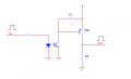
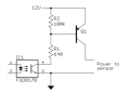
I attach two schematics. Which one offers better performance? The difference is the placement of some resistors. But, what are the advantages and disadvantages?
I attach two schematics. Which one offers better performance? The difference is the placement of some resistors. But, what are the advantages and disadvantages?
Attachments
-
 3.3 KB Views: 29
 -
 9.9 KB Views: 29


