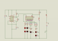
Are we supposed to take a circuit that, apparently, is not working correctly and figure out not only what it is doing but what you wanted it to do in the first place?
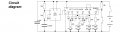
the 555 works as an oscillator, in this case it is supposed to run fast enough so that users/players cannot choose when to stop the roll.
4017 is decade counter and decoder but can be forced to count to less than 10 (in this case Q6 is tied to reset so counter will reset when Q6 is active).
resistors and LEDs are used for indication.
rectifier diodes are used as OR gates to drive indicators.
button is normally open so counter is not disabled and keeps on counting (remember that oscillator is very fast, at least for human eyes). when button is pressed, counter freezes (stops counting) and present state as indicated by LEDs can be easily read even by slow human eyes.
"A" LED is supposed to be in the center of the "H" pattern (used in numbers "1", "3" and "5").
"B" LEDs are on ends of one diagonal etc. (when B, C and D are all on, displayed value is "6").
I simulated the circuit on proteus and it doesnt work very well.
Look at your circuit. When Q3 is High, 3 LED have to be ON and when Q4 is High, 4 LED have to be ON. There are cases when 6 LED have to be switched on at the same time. As 4017 is a CMOS IC, the output current is very limited and the LED are just dimly lighted when more than one LED is switched on.
The 10nF on pin 2 of 555 is also too low for my simulator. I have to change it to 100nF (0.1 uF) for it to work.
You can try it on breadboard and use transistors to drive the LED to get better brightness.
yes, this is a poor circuit indeed. it has other problem such as enabling cheaters to cheat and then you have a constant fight over what the outcome really was.
it only takes minor modification to oscillator circuit and produce roulette effect for example. then circuit "spins" fast while button is pressed. when button is released, it should continue to count for a while (perhaps 3-4 seconds) before stopping (long enough that players hand is a safe distance away). the LED brightness can be addressed without addition of transistors by choosing high efficiency LEDs (ones that need no more than 2-3mA for example) and increasing value of series resistors.

 Facebook
 Google
 GitHub
 Linkedin
 122.2 KB Views: 120