Facebook
 Google
 GitHub
 Linkedin
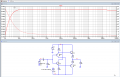
Hi guys, i'm trying Multisim but this circuit ( 5 - Diamond Buffer ) i drew do not work in output. Yet it seems to me that I have drawn it correctly. Including the position of the transistors. Any suggestions? Thank you.
Source https://sound-au.com/articles/followers.html#s5
Source https://sound-au.com/articles/followers.html#s5
Attachments
-
 88.7 KB Views: 17