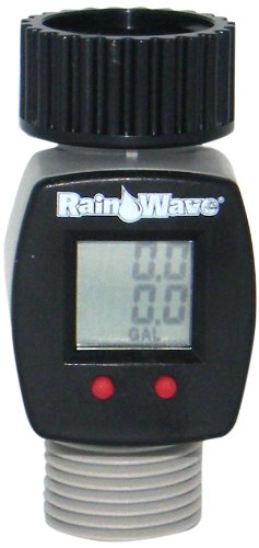
Thanks, I just saw it at the Amazon Mexico website too, and at the same price. I might just buy it to hack into it, like you've suggested. Besides, I'm a prime member and delivery is free and on the very next day
I've noticed that some hall sensors stop detecting when they're exposed to magnetic fields continuously for too long... that's why I'd like it to wiggle, but I'm going to make sure and test it.
Well, in this case there is access to the internals of the pipe. And my question is, other than a paddle or a turbine, what else is there that I could use to detect its motion?
How about allowing a movable obstruction (like a magnetic piston) that can be pushed downstream by the flow, and that an external electromagnet can return to the starting point when you sense the travel limit has been reached?
How about allowing a movable obstruction (like a magnetic piston) that can be pushed downstream by the flow, and that an external electromagnet can return to the starting point when you sense the travel limit has been reached?
Thanks, I had already considered that. In fact, that's the technique most on-demand water heaters use, but they use a reed switch instead of a hall sensor. But there's a strange thing going on with the sensor I chose. The sensor is active low, and if it's exposed to a steady magnetic field for too long, then it will stop detecting and go back to its normal high state. So it's important that the magnetic field fluctuates. Besides, its fluctuation frequency can give a rough indication of the rate of flow.
I didn't read through all the suggestions, so if this has already come up please excuse.
I wonder if you might consider a heated tiny thermistor poked through a little hole in the pipe. In still water the thermistor would be warmish. In flowing water the thermistor would be cooled. That should give you the flow/no flow signal.
^^^ If you want a rough estimate of flow rate you might try a second un-heated thermistor a bit upstream of the heated one. The delta should be proportional to flow rate.
^^^ If you want a rough estimate of flow rate you might try a second un-heated thermistor a bit upstream of the heated one. The delta should be proportional to flow rate.
Thanks. In fact, I built a circuit exactly like the one you've described a few years ago, except that it worked with two transistors and not a thermistor. And it worked like a charm to measure the flow of air. But this application is battery-powered, so current draw is critical, and therefore this technique is off the table.
Just chiming in on this thread, but: (first 90 seconds are the point) Beyond detecting the slightest movement, which they seem to know when I have a dripping faucet, you can later upgrade to measuring the amount of water to have passed through. Perhaps the water company might have some older models they would part with for cheap. You don't seem to care about accuracy, so - - - .
But there's a strange thing going on with the sensor I chose. The sensor is active low, and if it's exposed to a steady magnetic field for too long, then it will stop detecting and go back to its normal high state.
What sensor are you using? I've never experienced that behavior with any of the hall effect sensors I've worked with. It reminds me of the way capacitive touch sensor circuits are often designed to be self-calibrating constantly, meaning they can only be used for intermittent signals that are mostly off.
If I were in your shoes, I'd be shopping for a different sensor that behaves normally. For all the time and effort you're putting into this project, you shouldn't be limited by the behavior of one quirky sensor. If the sensor does exactly what you want, that's great; but if it's preventing you from using methods that would otherwise be viable (and it sounds like it is,) I think you should seriously consider scrapping it.
What sensor are you using? I've never experienced that behavior with any of the hall effect sensors I've worked with. It reminds me of the way capacitive touch sensor circuits are often designed to be self-calibrating constantly, meaning they can only be used for intermittent signals that are mostly off.
If I were in your shoes, I'd be shopping for a different sensor that behaves normally. For all the time and effort you're putting into this project, you shouldn't be limited by the behavior of one quirky sensor. If the sensor does exactly what you want, that's great; but if it's preventing you from using methods that would otherwise be viable (and it sounds like it is,) I think you should seriously consider scrapping it.
Thanks for the suggestion. The sensor I'm using is the SM351LT, and the reason I chose it is because it works at an extremely low power, in the order of 360 nA. And the glitch itself does not affect the function I want it to perform, since the presence of flow means that the sensor will be constantly switching on and off anyway. It doesn't matter which state it's at when at rest.
Thanks for the suggestion. The sensor I'm using is the SM351LT, and the reason I chose it is because it works at an extremely low power, in the order of 360 nA. And the glitch itself does not affect the function I want it to perform, since the presence of flow means that the sensor will be constantly switching on and off anyway. It doesn't matter which state it's at when at rest.
Cool, thanks for the info! I forgot that you mentioned low power consumption being a top priority. That certainly narrows the options quite a bit.
I am still intrigued by the behavior you describe. Nothing in the datasheet makes it sound like it should be doing that. I'm not clear on when it goes in and out of "sleep mode," so maybe if I understood that better it would help explain the odd behavior.
Sounds like it doesn't matter for your application, but I'm just curious for my own interest now. Among other things, I'm wondering if there's some secondary effect coming into play, like a nearby piece of ferrous metal which reacts slowly to the changing magnetic fields and gradually skews the sensor reading. I love a good mystery!
Cool, thanks for the info! I forgot that you mentioned low power consumption being a top priority. That certainly narrows the options quite a bit.
I am still intrigued by the behavior you describe. Nothing in the datasheet makes it sound like it should be doing that. I'm not clear on when it goes in and out of "sleep mode," so maybe if I understood that better it would help explain the odd behavior.
Sounds like it doesn't matter for your application, but I'm just curious for my own interest now. Among other things, I'm wondering if there's some secondary effect coming into play, like a nearby piece of ferrous metal which reacts slowly to the changing magnetic fields and gradually skews the sensor reading. I love a good mystery!
Maybe (and I'm just guessing here) the strange behavior manifests itself because perhaps I'm using too strong a magnet, and it's somehow saturating the sensor. I'm also sure that its internal circuit is self-calibrating somehow, and that's what's causing the anomaly.
Yeah, I noticed that too, but forgot to mention it. I'm not sure if it makes much difference to the overall project since all the analog stuff is handled internally within the sensor, and it has a flip flop driven push pull output.

 Facebook
 Google
 GitHub
 Linkedin