I'm trying to make some LED lighting systems for my pantry and linen closet; I've got some nice cheap strings of 12V LED modules from MPJA and a 12V/3A power brick.
To make the lights turn on when the door opens and off when it closes, I figured a magnetic switch would be good because they're already designed to be used on doors. I had to shop a bit to find a NO/NC type, but found one that will work; however, the LED strings are rated at 1.6A and the reed switch is only rated for 0.75A.
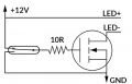
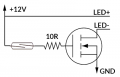
My first idea is to use a MOSFET to switch the LEDs... is this a good plan? If so, I'm figuring the NC contact (circuit opens when magnet is brought near) of the reed switch can drive the gate of the MOSFET to switch the LEDs. I wanted to use a MOSFET instead of a relay to avoid the clicking sound, and also to minimize moving parts.
Is this schematic sufficient?
To make the lights turn on when the door opens and off when it closes, I figured a magnetic switch would be good because they're already designed to be used on doors. I had to shop a bit to find a NO/NC type, but found one that will work; however, the LED strings are rated at 1.6A and the reed switch is only rated for 0.75A.
My first idea is to use a MOSFET to switch the LEDs... is this a good plan? If so, I'm figuring the NC contact (circuit opens when magnet is brought near) of the reed switch can drive the gate of the MOSFET to switch the LEDs. I wanted to use a MOSFET instead of a relay to avoid the clicking sound, and also to minimize moving parts.
Is this schematic sufficient?
Attachments
-
 16.9 KB Views: 6