By changing the 7809 with a 7815 and the value of R3 to 2.7Kohms, a 10V range is obtainable at the output.
However i need help in the current settings, from what i observe R3 holds a portion of the supply voltage, giving the potentiometer it's min voltage setting and the max voltage setting comes from the supply line. so that's how a 5.6v to 8V range is achieved.
what i am missing in knowing how to change the current values..
Go back to post #9, that is the root schematic. R2+R3 set a voltage across R1, the voltage across R1 sets up a constant current. We're going in circles here. Part of the problem is I'm not sure how much base theory you have, such as voltage dividers and transistors. You really need to get these basics down, otherwise no amount of explination is going to help.
Ya i have to admit still being in the beginning level but not giving up to learn, but anyway i have design the circuitry to perform to my desire after many reading on the electronic books and experiments.
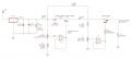
Following the same designs, here are my values below.
Is there any suggestion to this circuitry and the key thing which i found out is the impedance of the op-amp with R6 has to be extremely huge which is unbelievable.
Is there any suggestion to this circuitry and the key thing which i found out is the impedance of the op-amp with R6 has to be extremely huge which is unbelievable.
I have tried using a 100KΩ for R6 at first which i got a 70mA output reading, this is due to a voltage drop which is huge across the resistor which is unwanted.
So i increase the values of the resistor R6, till it was in it's Mega range and slowly till i got 20mA output readings.
I believe this is due to the reason to try to get a really high impedances to disallow any current or voltage to activate Q2. What shock me is that my school has only 10MΩ in the local radio shack and i had to use almong 10 pieces in series.
OK, I understand. R6 is only in there for when you go into current regulation mode. It limits the interaction the op amp has with the output. It is actually pretty straightforward, the op amp will output whatever voltage you are set for (say 5V by way of example), and since the output is low (say it is shorted, by way of example), there will be current coming from both the op amp and Q1. The original specifications in post #65 defined 100KΩ. 5VDC minus .7V (Q2 BE drop) divided by 100KΩ is 43μa. This is how much it would be off.
I suspect some of your values aren't what was originally defined. Within limits much of this circuitry is extremely predictable. Remember, the current control takes precidence over voltage, if you try to draw too much current it goes into constant current mode, and will regulate to whatever the current control is set for.
I suspect some of your values aren't what was originally defined. Within limits much of this circuitry is extremely predictable. Remember, the current control takes precidence over voltage, if you try to draw too much current it goes into constant current mode, and will regulate to whatever the current control is set for.
i believe i know what you mean. I am having this adjustment at the moment which allows me to only adjust both my current and voltage values at the same time with only 1 potentiometer which is R5.
R2 however is fixed to 21mA and cannot be adjusted.
Does this in a case makes the circuit still as it is in another way, adjust both the desire values at a same time which allows me to also replace R2 with a simple 10K resistance and a wire connection to Q1 base. I believe it is possible, isn't it.
OK, the voltage on the base of Q1 is fixed. It and R1 define what the current setting is. The current setting is defined by...
Iset = (V(base of Q1) - .6V(BE of Q1)) / R1
If the current is below this value then Q1 is saturated, not in linear mode. When you try to exceed the current Q1 goes into its linear mode, and regulates the current to the setting. At this point the collector will drop to whatever it needs to be to match the current to the setting. You can even short this point to ground, and see what the current setting is.
This circuit is extremely modular, each regulator (current and voltage) does its job with a minimum of interaction.
R7, your load, is a fixed 10k resistor. The more voltage you put across R7, the more current will flow through the resistor, up to whatever current limit is set by R2.
I=E/R. So, if you have your current limit set to allow 1mA or more current, you should be able to raise the output voltage to 10v. 10v/10,000 Ohms = 1mA.
I don't know why you say that R2 is fixed and cannot be adjusted; you show it as being a potentiometer in the schematic.
Sorry guys, lots of mistake on my circuit. I am making use of EAGLES to just show an illustration as i am really limited in school due to the admin right which prevent me from installing more software.
Hmm the potentiometer that can adjust voltages 0 to 11V in the voltage regulator section is R5, my apologizes.
The experiment was done on a board with components, and what i got was a reading of 0V to 10V and a 0A to 21mA as stated in the circuit.
However the adjustment of R3 will have no effect on the current at the output.
Only R5 makes an adjustment of both the voltage and the current values at the output.
R3 on the other hand is able to adjust the voltages at the point of the first op-amp as shown as well but not able to adjust the output current or the voltage.
Without setting the potentiometer of R3 to either it 11V or 14V.The output voltage produced with the current as well can only be adjusted with R5. I tried using a current meter and a voltmeter, it perform exactly the way i mention.
R3 in that case seems to be of no use while R5 seems to be the one in control of both the current and the voltage at the output.
I am kind of asking myself why too... Cause when i made my calculation on the circuit resistor, i did notice a voltage on R6(about 1.4V), so i connected more resistance to the circuitry which made the current value drop from a 70mA to a 21mA. (100KΩ to 105.2MΩ) I did this to increase the impedance on the Op-amp which i found out that it has an effect on the current output readings as well too..
This is strange but it does perfrom to what i am looking for without any problem.
Bill,
Looks to me like he drew the schematic using Cadsoft's Eagle Layout Editor, which can be downloaded for free, and used in a (limited) freeware mode (1-sheet schematics, PCBs limited to 2 layers, 3"x4").
You can use it to generate schematics and PCB layouts, but SPICE for it is an add-on by another software house, Beige Bag Software, and I have no idea how good it is. http://www.beigebag.com/
There are trial versions that will work for 30 days (if you register within 5 days)
There is a "lite" version that's limited, won't interface with Eagle, but is free.
The standard version is $250, the pro version $400.
But thanks anyway guys , i understand how the current and volatge regulator works and have tried buliding it while calculating it. Works indivdually but when joining them up i had this challenge.
This circuitry came out from my discovery only when i notice a voltage at R6 which i tried to increase the impedance. And well this happened.But any theory explanation to this?
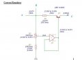
I believe my problems for the circuitry lays here.. Accroding to Bill's design as in post 40, the Q1 will set a constant current to R1 and a constant current at the transistor collector.
However according to measurement of my current regulator that isn't so. I hope that i am right through calculation Ie=Ic+Ib is correct too and it tells me a different story.
What are you using to measure the current?
You can't have 19mA into the emitter, that same 19mA flowing out of the base, and still get 0.98mA out of the collector. Transistors don't generate current.
What are you using to measure the current?
You can't have 19mA into the emitter, that same 19mA flowing out of the base, and still get 0.98mA out of the collector. Transistors don't generate current.
Well an ammeter and i am well aware that it has to be connected in series in order to measure the current. But is there a way you can suggest me to measure the current.
One way that i know off is to include a resistor and measure the voltage across it while using ohms's law to make a calculation on the current on that path.
 Facebook
 Google
 GitHub
 Linkedin
 but it does perfrom to what i am looking for without any problem.