Facebook
 Google
 GitHub
 Linkedin
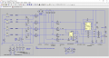
Hieetech00, I am having problem on the Opto-Isolator input voltages. I am using ISQ5 from Isocom Dual Transistor Output Opto-Isolator and the forward voltage is 1.2 Volts. What I am getting right now is 1.016 Volts. Can you make a simulation if I used a 33K or lower resistance to get more than the required minimum voltage for the Opto_Isolator? Also that the reset signal requirements should be to switched off the negative power rail.
The datasheet doesn't have a graph showing the CTR. But at 1ma input current there will be 40% CT, so that's about 400uA for the output which should be plenty for the CMOS device inputs. I agree with Alex_T, the 36k or 33k should be fine, you don't need much current.