Designing a simple alarm signalling circuit

Thread Starter

nestbulala

Joined Dec 12, 2015
111
Hi Alex_t

I think the latch circuit in post #44 is missing a (1uf) cap from the collector of Q2 to +V.
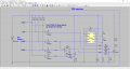
eetech00, I have tried the capacitor on Q2 collector, Q1 base, Q2 base on ground and positive but gives no result. The only thing that will latch the circuit is the R7 from collector of Q1 to the base of Q2 after the first half cycle of the signal. It flash for the first time and the second time it became steady lit without pressing the acknowledge button.
 

Alec_t

Joined Sep 17, 2013
14,313
Were you using the suggested capacitor with R7 in place? The circuit should need both present: not just one or the other.
 

Thread Starter

nestbulala

Joined Dec 12, 2015
111
Were you using the suggested capacitor with R7 in place? The circuit should need both present: not just one or the other.
I did test it without the R7 because it latches even you did not pressed the Acknowledge. But when I connect the capacitor to the base of Q2 to positive together with R7 as you mention, it latches and it is working as what you have simulated. Thank You Very Much for you guys especially Alec_t and eetech00 for your design insights. I think we can say that the project is completed and I will finalize it in PCB. There is one more thing though about the R3 in series with the LED's 2K7, 1W to the positive rail, it is getting hot. I supposed to replace it with a 3 Watt would that be possible?
 

Thread Starter

nestbulala

Joined Dec 12, 2015
111
Alec_t, eetech00, I found another problem, the lamp latches after 15, 20 or 40 flashes even you did not press the Acknowledge.
 

Alec_t

Joined Sep 17, 2013
14,313
I supposed to replace it with a 3 Watt would that be possible?
Yes. Good idea.
Glad you've now got it working.

Edit:
Just noticed you latest post. You do like creating mysteries, don't you? :D.
It's possible the cap you just added is leaky. Try connecting it instead between Q2 base and ground.
 

Thread Starter

nestbulala

Joined Dec 12, 2015
111
I have used maybe all possible connections for the R7 and the Cap but no good result. It is not stable. I maybe going to the idea of an SCR and I will keep you posted.
 

eetech00

Joined Jun 8, 2013
3,949
Hi

imo...if it doesn't work with the original circuit I don't think the using an SCR is going to make a difference. You need to find out what is "unstable".

You can try this version if you wish but will need more components. It uses a CD4093B and CD4013B and opto's to interface to the control signals. The 48vdc is regulated down to 12vdc. I didn't show it, but you'll need a 0.1uF cap from +V to ground at each chip. The reset button is the same as the other buttons and resets the FF instead of breaking the ground rail. I would breadboard it and test on a bench first.
 

Attachments

Thread Starter

nestbulala

Joined Dec 12, 2015
111
Just noticed you latest post. You do like creating mysteries, don't you? :D
Alec_t, I do like creating mysteries:D It is a hobby, past time, do mistakes and learn as you go along and be happy when your project works, right? but I am very grateful that you guys and in this forum are very helpful for a guy like me to help and give your best shot of advice.

eetech00, I have previously thought of this design without the 4093. In fact there is already a PCB for it. I am just waiting for the 4093 and some caps and I will keep you posted.
 

eetech00

Joined Jun 8, 2013
3,949
eetech00, I have previously thought of this design without the 4093. In fact there is already a PCB for it. I am just waiting for the 4093 and some caps and I will keep you posted.
Hi

I went ahead and tested the logic on the bench using the 4093, 4013, and 555 circuit as shown on the schematic, post #68, with a 12Vdc power supply. The circuit works exactly as shown on the simulation. I didn't test with the opto's or the transistor regulator because I didn't have the parts. But I think the circuit will work like you want. Also, the 2N7000 N channel would probably be a better choice for the mosfet driver.
 

Thread Starter

nestbulala

Joined Dec 12, 2015
111
eetech00, I have tested the circuit and I have a continuous flashing even without alarm and when I pressed the lamp test button the lamps went off. It might be inverted by the schmidtt trigger could it be.. right? that was the case before connecting the 4013. I think I will nail it later.
 
Last edited:

eetech00

Joined Jun 8, 2013
3,949
eetech00, I have tested the circuit and I have a continuous flashing even without alarm and when I pressed the lamp test button the lamps went off. It might be inverted by the schmidtt trigger could it be.. right?
I've tested the circuit on the bench as shown on the schematic so I know it works as intended.
It sounds like you may have the inverters connected incorrectly or the opto's not connected incorrectly.

Check the supply voltages and perform a systematic check of the alarm input circuit.
When the alarm contact is open, there should be a few millivolts (~5mv) at the output of inverter U3.
This holds the timer in "reset" mode causing the LED to be off.

When the alarm contact closes, the input of U3 should go low (~5mv) and the output of U3 should go high (~12v) causing the LED to flash.
The acknowledge button toggles the flip flop (via inverter U2) if the RST line is high, causing the "ACKE" line to go high, which overrides the flash and causes the LED to light steady.

The reset button simply resets the FF, causing the "ACKE" line to go low, and allows the ALME line to flash the LED if the timer is not in reset mode.

Measure the input/output voltages of each inverter circuit one at a time and make sure the voltages are as expected under the open and closed conditions of the input contacts. Make sure there are bypass caps (0.1uf) across the supply pins of each chip.

This is a pretty straight forward circuit. Report back what you find.
 
Last edited:

Thread Starter

nestbulala

Joined Dec 12, 2015
111
The U11 inverter output always high going to CLR of fliflop. Regulator gets hot need to figure out. When the ALRM and Lamp Test closed voltage down to 2.15.
 

eetech00

Joined Jun 8, 2013
3,949
The U11 inverter output always high going to CLR of fliflop. Regulator gets hot need to figure out. When the ALRM and Lamp Test closed voltage down to 2.15.
The regulator is dropping about 36v across it so it will run hot if it doesn't have a heat sink, otherwise that's normal. Put a good 6W heat sink on it so it doesn't burn up.
An alternative is to use a switching regulator (more complicated) or a small DC-DC converter. The DC-DC converter is the simplest and doesn't require a heatsink but costs about $10 US. Another option is to use a 12vdc wall wart.

Remember, U11 is an inverter, so if the output is high, the input must be low or the part is bad.

Separate the circuit into two sections...a 12v supply section and a 48v supply section. Troubleshoot the 12v circuit with only a 12v supply (don't use a 48v supply) and get it working first. None of the chips like 48v and can damage easily.

See attached. Just build the 12v section first and get it working.
 

Attachments

Last edited:

eetech00

Joined Jun 8, 2013
3,949
Hi

Attached is a version that uses a wall wart (AC adapter) to power the circuit.
I've also reordered the reference designator and added voltage level annotations to help check voltages.
 

Attachments

Thread Starter

nestbulala

Joined Dec 12, 2015
111
eetech00, I am having problem on the Opto-Isolator input voltages. I am using ISQ5 from Isocom Dual Transistor Output Opto-Isolator and the forward voltage is 1.2 Volts. What I am getting right now is 1.016 Volts. Can you make a simulation if I used a 33K or lower resistance to get more than the required minimum voltage for the Opto_Isolator? Also that the reset signal requirements should be to switched off the negative power rail.
 
Top