 Facebook
 Google
 GitHub
 Linkedin
Dear Experts,
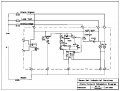
I am designing a simple alarm signalling circuit for our legacy alarm board. I am very much concern about the scr and the latch circuit if it does what I am expecting. Can anybody advise on the attached circuit?
I am designing a simple alarm signalling circuit for our legacy alarm board. I am very much concern about the scr and the latch circuit if it does what I am expecting. Can anybody advise on the attached circuit?
Attachments
-
 83.5 KB Views: 95


") .
.


