ErnieM, I have started to write the code using XC8 compiler and I am stuck with the delay in flashing the LED. This is my first programming experience so please bear with me.
ErnieM, I have started to write the code using XC8 compiler and I am stuck with the delay in flashing the LED. This is my first programming experience so please bear with me.
Yes, spinnaker, the LED is not getting turn off if the alarm signal or GP0 is low. It should be turning off only when reset GP3 and GP0 is low.
Please find the attached code including delays and other buttons. It compiled successfully but I don't know if it work in microcontroller.
eetech00, I tried to compile the code but I got stuck on page 84 for some unexpected syntax. Please analyze what could have been missed. I am also having problem on the else statement and the MCLREN=LL.
eetech00, I tried to compile the code but I got stuck on page 84 for some unexpected syntax. Please analyze what could have been missed. I am also having problem on the else statement and the MCLREN=LL.
You need to learn to analyze yourself. This is a simple (and common) mistake that is easily found. Your editor should have a bracket pair matcher. If it does not then get an editor that does. In MPLab editor place your cursor on one bracket. The corresponding bracket will be highlighted.
if(GPIO2 == 1) // if Lamp Test is high
{
__delay_ms(100); // de bounce for 100 ms
{ // <<<<< Looks like extra bracket.
GPIO5 = 1; // Output to LED is high
}
And the error should not be "unexpected syntax" it should be "unexpected end of file". an unexpected end of file most times means an unmatched bracket.
eetech00, I tried to compile the code but I got stuck on page 84 for some unexpected syntax. Please analyze what could have been missed. I am also having problem on the else statement and the MCLREN=LL.
eetech00, some minor changes, compiled and tested in the circuit and found the following:
1) Alarm GP0 is pressed, GP5 flashes quickly. Required condition GP5 flashes one second off, one second on.
2) Alarm GP0 is released, GP5 steady lit. Required condition GP5 should remain flashing.
3) Ack GP1 is pressed, no action. Required condition GP5 should be steadily lit.
4) Lamp Test GP2 is pressed, GP5 lamp goes off. Required condition GP5 Lamp should be on.
5) MCLR GP3 is pressed, no action. Required condition should reset the CPU and GP5 should be off if Alarm GP0 is off too.
I will try to play with the timings and maybe interchanged the GP2 and GP3 if I get good results.
eetech00, the latest changes does not work at all. The previous one main_v2 only the GP5 flashes when GP0 is pressed and off if released. It should latch and remain flashing until acknowledge have been press. Other functions like ack and lamp test reverse output.
eetech00, the latest changes does not work at all. The previous one main_v2 only the GP5 flashes when GP0 is pressed and off if released. It should latch and remain flashing until acknowledge have been press. Other functions like ack and lamp test reverse output.
It worked as expected using the MPLAB simulator to test.
Are you using the MPLAB simulator to test? or an ICD?
I don't think you are initializing the simulation correctly.
1. Start the simulator.
2. pause the simulator
3. set all I/O (input) pins to "1"
4. "reset" simulator
5. "continue" the simulator
After step 5 above, you should see GP0-3 = 1, GP5=0
If you then "fire" GP0= 0, GP5 I/O pin will alternate between 1 and 0 indicating a pulsing output state.
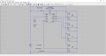
I'm attaching a revised schematic. It has been revised to show the PIC connections as well as a modified relay control circuit.
The relay will de-energize (and the PIC will reset) when the reset button is pressed.
I'm also attaching modified source code. This code was compiled and tested on a PIC12F629 and operates per your requirements.
Hi eetech00, Code was downloaded to the target and when power up, GP5 steady on, push the Alarm GP0 and it flashes, push the Ack GP1 it reset and GP5 LED is off. other buttons no action. I may have been doing the wrong way in compiling and downloading but some of my projects works by the same way. I don't know why it work for you and mine is not. That maybe you can call it experience. I may do it persistently to get my results. Will you please upload the asc file for the circuit.
 Facebook
 Google
 GitHub
 Linkedin