 Facebook
 Google
 GitHub
 Linkedin
Hello everyone,
I'm a professor in a french university, every year our student are working on a wind turbine (urban) competition.
Our wind turbine is working very well, everything is done by us (electronics, generator, blades etc...)
We are still strugling on the electronic converter, we need a buck converter in order to allow the wind turbine to work in a good condition.
We use an arduino with a 33000hz switching frequency, we need to vary the output voltage between 0-100%.
The input is between 0V-80V, the current is 0-25A.
Our actual buck converter is not good enough, we used a mosfet at the ground side to be able to switch it, and a shotky diode. It is only 85% efficiency, we want a much higher efficiency (the cost is not a problem).
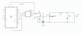
Our new design is looking like this:
MOSFET IRFP4110
Self: Epcos, 0,57 mH, 35A, 100kHz, 1,4mΩ Rdc
Capacitor: 22µF (any idea the best techno choice?)
Driver: MIC4424YN 3A
Diode: STPS61150CW
Any idea or help would be great. Thanks
Stephan
I'm a professor in a french university, every year our student are working on a wind turbine (urban) competition.
Our wind turbine is working very well, everything is done by us (electronics, generator, blades etc...)
We are still strugling on the electronic converter, we need a buck converter in order to allow the wind turbine to work in a good condition.
We use an arduino with a 33000hz switching frequency, we need to vary the output voltage between 0-100%.
The input is between 0V-80V, the current is 0-25A.
Our actual buck converter is not good enough, we used a mosfet at the ground side to be able to switch it, and a shotky diode. It is only 85% efficiency, we want a much higher efficiency (the cost is not a problem).
Our new design is looking like this:
MOSFET IRFP4110
Self: Epcos, 0,57 mH, 35A, 100kHz, 1,4mΩ Rdc
Capacitor: 22µF (any idea the best techno choice?)
Driver: MIC4424YN 3A
Diode: STPS61150CW
Any idea or help would be great. Thanks
Stephan


 ).
).


