Facebook
 Google
 GitHub
 Linkedin
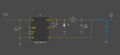
I’m working on a project where I need to step down 24V to a stable 5V with a load current of up to 1A. I’ve decided to use a buck converter based on the LM2675 IC. Here is my schematic made in DipTrace:

Input: 24V (DC)
Output: 5V / 1A
Controller: LM2675
Switching Frequency: 260 kHz
I’m planning to use two capacitors:
Input Capacitor (C1): To smooth the input voltage and suppress noise.
Output Capacitor (C2): To smooth the output voltage and minimize ripple.
I have the following questions and concerns:
Type and value of the input capacitor: I’m considering using a 100 µF electrolytic capacitor with low ESR, but I’ve heard that ceramic or polymer capacitors might be better for high-frequency applications. Which type would be optimal for input noise suppression?
Type and value of the output capacitor: Given the need to minimize output ripple, should I use multiple low ESR ceramic capacitors or a single large electrolytic capacitor? Or perhaps a combination of both?
Impact of switching frequency on capacitor selection: How does the 260 kHz switching frequency affect capacitor choice? Should this be a factor when determining capacitance?
Temperature stability: The system will operate at elevated temperatures (up to 70°C). Which type of capacitor is best suited for these conditions?
I’d appreciate any advice or suggestions! I’m especially interested in hearing from anyone who has experience with similar circuits.
By the way, how do you like DipTrace 5? Has anyone tried working on it yet?