Designing 3 24v analog input to single output

eetech00

Joined Jun 8, 2013
4,716
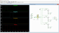
Is this what your trying to make?

The 57.6 ohm resistors represent load resistors for each mosfet output.
I have no idea what the value of the zener is so I used 24v thinking it was a supression diode.

1658514897643.png
 

Thread Starter

patelankur2603

Joined Jun 6, 2022
40
Is this what your trying to make?

The 57.6 ohm resistors represent load resistors for each mosfet output.
I have no idea what the value of the zener is so I used 24v thinking it was a supression diode.

View attachment 272038
three diodes connected work but the resistance needed was 60 ohms . It does not work with 10k resistor. The spray activates around 60 ohms and less.
 

crutschow

Joined Mar 14, 2008
38,624
The diodes are connected properly in right direction and then combined with resistance.
I show no combining resistor, only a resistor to ground where the diodes are tied together.

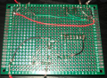
(After looking at the picture of your breadboard, I suggest you look at a Youtube tutorial on how to solder.
That is not a good soldering job. You are using too much solder for one thing.
Below is an example of how good solder joints look).

1658515362364.png
 

eetech00

Joined Jun 8, 2013
4,716
three diodes connected work but the resistance needed was 60 ohms . It does not work with 10k resistor. The spray activates around 60 ohms and less.
If 24v is feeding each diode of the "diode OR" gate then it should work as I've shown, unless whatever is connected to the "fault" wire is loading it down. So...can you draw the circuit that is connected to the "fault" wire?
 

BobTPH

Joined Jun 5, 2013
11,601
You do not need a resistor. Just put a diode with anode to each input and the 3 cathodes connected together to the output.

If each input can source the current required by the output, it will work.
 

Thread Starter

patelankur2603

Joined Jun 6, 2022
40
You do not need a resistor. Just put a diode with anode to each input and the 3 cathodes connected together to the output.

If each input can source the current required by the output, it will work.
Yes, I got the value 24v with only diodes. What if I need to add a protection circuit so that over voltage and current does not damage the diodes.
 

BobTPH

Joined Jun 5, 2013
11,601
Put a fuse in line with the output. Size it larger than the required output current and smaller than the diode rating.
 

eetech00

Joined Jun 8, 2013
4,716
You do not need a resistor. Just put a diode with anode to each input and the 3 cathodes connected together to the output.

If each input can source the current required by the output, it will work.
I put the resistor in to not allow the diodes to "float".
 

BobTPH

Joined Jun 5, 2013
11,601
As long as the load is connected, they do not float, but the 10K resistor is fine. Change it 60 Ohms, as the TS did, and it becomes a problem.
 

BobTPH

Joined Jun 5, 2013
11,601
I don’t know why you are shouting. Once a load is connected, any diode will have some voltage drop and you will not t get the full 24V. Using Schottky diodes will minimize the drop.
 

Thread Starter

patelankur2603

Joined Jun 6, 2022
40
I don’t know why you are shouting. Once a load is connected, any diode will have some voltage drop and you will not t get the full 24V. Using Schottky diodes will minimize the drop.
I am really sorry if it felt like I am shouting, but I am not. I appreciate the help and will be working on that. Will definitely let you know if encountered a problem.
 

MisterBill2

Joined Jan 23, 2018
27,898
The description of requirements seems to require a three input diode "OR" gate, which will allow the other outputs to be unaffected when one jumps to +24 volts. That part is simple.
If the input pair that has jumped to +24 volts stays at that high level, then indicating it will be simple. A series circuit with an LED, a resistor, and a 20 volt zener diode will work. At 24 volts the zener diode will allow current to flow, the LED will illuminate, and the resistor will limit the current.

 
Top