i have not yet calculated the exact value but around 420 mA of current would be fine. i will be powering it through external regulator which is 24v/2.5A O/P
For that you want a higher current diode for the circuit I posted, such as a 1N400x (x = 1 through 6) or a Schottky diode such as the 1N5818 (which has a slightly lower forward voltage drop).
For that you want a higher current diode for the circuit I posted, such as a 1N400x (x = 1 through 6) or a Schottky diode such as the 1N5818 (which has a slightly lower forward voltage drop).
i have not yet calculated the exact value but around 420 mA of current would be fine. i will be powering it through external regulator which is 24v/2.5A O/P
It still is not clear to me if there is a single, common GND for all input signals, output signal, and power. Because of this, here's my suggestion.
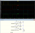
Three optocouplers, one for each input. The three output transistors in parallel drive a PNP power transistor (or power darlington) as the output switch. LEDs in series with each opto output will give an indication of which one is on. Schematic later, unless someone else wants to whip up one..
It still is not clear to me if there is a single, common GND for all input signals, output signal, and power. Because of this, here's my suggestion.
Three optocouplers, one for each input. The three output transistors in parallel drive a PNP power transistor (or power darlington) as the output switch. LEDs in series with each opto output will give an indication of which one is on. Schematic later, unless someone else wants to whip up one..
Exactly what I was getting at many posts ago. I asked if the inputs and outputs had a common or were isolated, and TS answered that is neither. I don’t think he understands what a common ground is, or what is meant by isolation.
He now says all the outputs come from a single chip, which implies they have a common ground.
We need to determine if this s true and if the output also shares a commonground before we can give a solution.
TS, if you understand what I am talking about, please inform us about the grounds. If not, tell us what you don’t understand.
Only if the three "sensors" make up only one electronic assembly. If they are three separate assemblies with independent power sources, then who knows.
The 2803 has 8 NPN open-collector darlington transistors with all of the emitters tied together. If this really is the output stage of a sensor module/assembly/whatever, then the output goes high by being pulled up when a transistor is turned off. This now raises the question of how much current is available to drive something like an optocoupler input.
OR
The sensor output is one stage of a 2803 that goes low on "sense". In the state where the TS says the output is 0 V, the actual case is that both output pins are at 24 V; one direct connect and one pull up resistor to a turned-off 2803 section.
I was gonna do a schematic, but now I'm holding off; still too many questions.
Exactly what I was getting at many posts ago. I asked if the inputs and outputs had a common or were isolated, and TS answered that is neither. I don’t think he understands what a common ground is, or what is meant by isolation.
He now says all the outputs come from a single chip, which implies they have a common ground.
We need to determine if this s true and if the output also shares a commonground before we can give a solution.
TS, if you understand what I am talking about, please inform us about the grounds. If not, tell us what you don’t understand.
Only if the three "sensors" make up only one electronic assembly. If they are three separate assemblies with independent power sources, then who knows.
The 2803 has 8 NPN open-collector darlington transistors with all of the emitters tied together. If this really is the output stage of a sensor module/assembly/whatever, then the output goes high by being pulled up when a transistor is turned off. This now raises the question of how much current is available to drive something like an optocoupler input.
OR
The sensor output is one stage of a 2803 that goes low on "sense". In the state where the TS says the output is 0 V, the actual case is that both output pins are at 24 V; one direct connect and one pull up resistor to a turned-off 2803 section.
I was gonna do a schematic, but now I'm holding off; still too many questions.
the wires should handle 0 to 24v , because inputs gonna give 24v supply when system activates and i need it to pass to output which is a spray module of 10 watts, 24vdc which in fact activates spray (water)
Only if the three "sensors" make up only one electronic assembly. If they are three separate assemblies with independent power sources, then who knows.
The 2803 has 8 NPN open-collector darlington transistors with all of the emitters tied together. If this really is the output stage of a sensor module/assembly/whatever, then the output goes high by being pulled up when a transistor is turned off. This now raises the question of how much current is available to drive something like an optocoupler input.
OR
The sensor output is one stage of a 2803 that goes low on "sense". In the state where the TS says the output is 0 V, the actual case is that both output pins are at 24 V; one direct connect and one pull up resistor to a turned-off 2803 section.
I was gonna do a schematic, but now I'm holding off; still too many questions.
i output current from each channel of 2803A is around 30 to 300 mA. but after that there are many resistors and diodes so there will be drop in the value. I am not worried about the drive current right now. I am trying to build a schematic of what components to use and how to workout the logic. Later on while testing, we can change accordingly.
What is the current rating of the unmarked p-channel MOSFET?
What is the cold value of the PTC?
Can the 24 V source in this schematic supply the current you need to power the spray module, or does the power for the spray module come from a different voltage source?
What is the current rating of the unmarked p-channel MOSFET?
What is the cold value of the PTC?
Can the 24 V source in this schematic supply the current you need to power the spray module, or does the power for the spray module come from a different voltage source?
its a power mosfet, IRFR9024NTRPBF . please check the datasheet attached for mosfet. PTC cold value is 0.5 ohm. 24v supplies the current i need to power the spray module. no external source is connected seperatley to spray circuit.
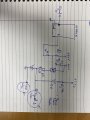
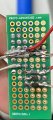
Check this, i am testing 2 modules for now . So did not connect third one. The diodes are connected properly in right direction and then combined with resistance.
i was testing and i found that due to resistor 10k 0.152 v was the output. I tried 100 ohm and got 9 v o/p . still i need 24v but when i tried 50 ohms it did not work.

 Facebook
 Google
 GitHub
 Linkedin