 Facebook
 Google
 GitHub
 Linkedin
I would like to have your opinion on some calculations I am doing on the unregulated output of a half-wave rectifier with filter capacitor.
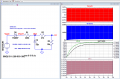
The diagram is as follows:

With Vsect = sinus wave with 311 vpk (220RMS).
I would like to calculate the output voltage V1. I have calculated the transfer function with Vrect1 as input:
V1(s)/Vrect1(s) = [R3/(R1+R2+R3] * [1/ (1+sC2(R1//(R2+R3)) )]
with a pole (wp) at 159m Hz and s= jw (w=2Pi*f)
In order to have V1, I put Vrect1 = 155VRMS (half-wave rectifier output) (=Vpk/2 = 311/2).

I calculate the modulus of the whole, with the frequency f=159m Hz, I find :
V1 = Vrect1 * ||[R3/(R1+R2+R3] ||* ||[1/ (1+sC2(R1//(R2+R3)) )]||
V1 = 155 * (36.1m) * ||(0.5-0.5 i)||
V1 = 155 * (36.1m) * 0.709
V1 = 3.967 V (which corresponds to the simulation).

But the problem is Vrect1. Is it correct to take VRMS for the voltage Vrect1 (or the average value VAVG?) in this case how to calculate this average value (Vrect1 avg) knowing that the filtering capacity introduces a DC voltage of 22V (see graph above).
In short, can you tell me what calculations have to be made to obtain the value of the output voltage V1?
Attached is the voltage curve at the edge of capacitor C2 (and the current IC2):

Thanks a lot!
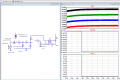
The diagram is as follows:
With Vsect = sinus wave with 311 vpk (220RMS).
I would like to calculate the output voltage V1. I have calculated the transfer function with Vrect1 as input:
V1(s)/Vrect1(s) = [R3/(R1+R2+R3] * [1/ (1+sC2(R1//(R2+R3)) )]
with a pole (wp) at 159m Hz and s= jw (w=2Pi*f)
In order to have V1, I put Vrect1 = 155VRMS (half-wave rectifier output) (=Vpk/2 = 311/2).
I calculate the modulus of the whole, with the frequency f=159m Hz, I find :
V1 = Vrect1 * ||[R3/(R1+R2+R3] ||* ||[1/ (1+sC2(R1//(R2+R3)) )]||
V1 = 155 * (36.1m) * ||(0.5-0.5 i)||
V1 = 155 * (36.1m) * 0.709
V1 = 3.967 V (which corresponds to the simulation).
But the problem is Vrect1. Is it correct to take VRMS for the voltage Vrect1 (or the average value VAVG?) in this case how to calculate this average value (Vrect1 avg) knowing that the filtering capacity introduces a DC voltage of 22V (see graph above).
In short, can you tell me what calculations have to be made to obtain the value of the output voltage V1?
Attached is the voltage curve at the edge of capacitor C2 (and the current IC2):
Thanks a lot!

")


