Design of an h bridge for an 12A motor

Thread Starter

Mr Once

Joined Dec 25, 2017
4
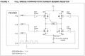
Hi guys, i'm trying to design an h bridge for an 12A 48V motor, this is not my area of expertice so i need some advice.

I'm thinking about this design

Captura de pantalla_2019-05-26_14-07-46.png

It is ok? I'm gonna use a PIC to drive de MOSFETS.

I chose the MOSFETS thinking that they should hold up to 12A*3 = 36A. Is this correct?

How i choose the diodes? They should hold up 36A too?

Thank you in advance.
 

crutschow

Joined Mar 14, 2008
34,468
What is the frequency of the signal you will send to the bridge.
What does the motor do?

The MOSFETS need a Vgs voltage at least 10v above Vin to fully turn on, so you will need a bootstrap driver for that, or change the top MOSFETs to P type.
You also need a driver for the bottom MOSFETs to provide the 10V Vgs turn-on voltage.

You generally don't need external diodes with MOSFETs as their internal source-drain substrate diode can perform that function.
 
Last edited:

Thread Starter

Mr Once

Joined Dec 25, 2017
4
Hi guys, thank you both for answering.

I think i'm going for the P channel MOSFET option since i could'nt find any driver here where i live and i need to have this working for thursday.

What is the frequency of the signal you will send to the bridge.
What does the motor do?
The frequency is about 20KHz, and it's a brushed motor for an electric car.

You also need a driver for the bottom MOSFETs to provide the 10V Vgs turn-on voltage.
Instead of the driver could i use just a transistor and a voltage divider to get the 10V out of the 48V (Vin)? It is not necesary for the top (P Channel) MOSFETS?

About the diodes, that was my first idea, but a colleague of mine told me it was a good idea to use the external diodes. So it is safe to rely on the internal diodes?

Thank you guys.
 

MaxHeadRoom

Joined Jul 18, 2013
28,700
Any reason for going 20Khz?
The Picmicro site has the Mechatronics board has firmware and software for an example in DC motor control..
Max.
 

crutschow

Joined Mar 14, 2008
34,468
To drive the MOSFETs at those frequencies you will need a high-current gate driver for all the MOSFETs to rapidly charge and discharge the MOSFET large gate capacitance, otherwise the efficiency will be low and the MOSFETs may overheat.

Look at the rating for the internal MOSFET diodes to see if it's sufficient.
 

MaxHeadRoom

Joined Jul 18, 2013
28,700
Have you also explored the App notes on the Pic site for DC motor control?
If you have to have it working by Thursday, it may be cutting it fine as the schematic in the OP won't work as posted.
You will still need the suitable gate drivers as well as the P.S. for them.
If not your area of expertise, it would be the most prudent to use a tried and true circuit, before trying to design your own.
Max.
 

Thread Starter

Mr Once

Joined Dec 25, 2017
4
Have you also explored the App notes on the Pic site for DC motor control?
Yes, that is the first thing i did and i found this


But, like i said, i could'nt find the MOSFET drivers here so i looked at the TOSHIBA notes for mosfets and the thousand designs i found on internet to try design my own.

If not your area of expertise, it would be the most prudent to use a tried and true circuit, before trying to design your own.
Max.
Totally agree, but all the circuits i found use the drivers i cant get, but looking at the bright side i'm learning a lot.

Look at the rating for the internal MOSFET diodes to see if it's sufficient.
Ok, but my calc its ok, the diodes should hold up to 36A?

And thank you again for your time.
 

Attachments

ronv

Joined Nov 12, 2008
3,770
Hi guys, thank you both for answering.

I think i'm going for the P channel MOSFET option since i could'nt find any driver here where i live and i need to have this working for thursday.


The frequency is about 20KHz, and it's a brushed motor for an electric car.


Instead of the driver could i use just a transistor and a voltage divider to get the 10V out of the 48V (Vin)? It is not necesary for the top (P Channel) MOSFETS?

About the diodes, that was my first idea, but a colleague of mine told me it was a good idea to use the external diodes. So it is safe to rely on the internal diodes?

Thank you guys.
Maybe something like this if you can find the transistors would be a way to interface with the 48 volts.
upload_2019-5-26_17-47-40.png

The problem with the divider is that the resistors get pretty big to keep the power down. When that happens the switching time of the FET gets slow.
Don't forget to program in some turn on delay in your program so the top and bottom FET don't overlap.
The clamp diodes need to be rated for at least 1/2 the motor current and their peak current higher than the maximum motor current.
 

Attachments

MaxHeadRoom

Joined Jul 18, 2013
28,700
That '12A' figure is most likely the normal running current. If so, you should allow for a much higher stall/start-up current, e.g. > 60A.
Although there is no need to see full current inrush at zero rpm using PWM, controlled acceleration can be used.;)
Max.
 
Top