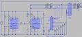
Much better, now I can read the IC labels. This circuit is very similar to what I was suggesting in #3. Nice to see it drawn out. I wasn't thinking of two timers, so kudos for that cleverness.
Thanks wayneh, yea the second timer is used to shorten the first timing cycle, because as you know, a 555 has a longer initial high period from power up in astable mode.
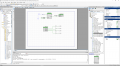
So here is a much cleaner solution than I posted earlier, seems to be working
fine.
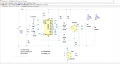
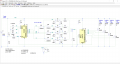
One chip, only externals are switch, cap to bypass chip power supply, and mosfets
or quad driver to handle led current. Schematic shown in tool is schematic of internal
resources used in the chip. Basically used small amount of chip resources as you
can see in the right hand window.
The timing accuracy / overlap between LEDs is << 20 nS. I sped up clock by 10
to take a measurement, and on 30 sec wide LED pulse (now 3 sec) measured
3.000 sec. So happened to be dead on.
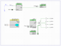
Here is another approach, make the LEDs brightness controled by external sensor,
like light, temp, V....... SAR translates sensor output to digital, and that is written into
PWM to control its duty cycle. In this case all LEDs brightness will be same same.
as each other when they are individually on.
Part I think has enough resources so you could set SAR for 4 channels, 4 sensor, and control
individually each LED brightness.
All while still doing sequence. In fact w/o code intervention could use DMA to
automatically update PWM with SAR value. Lots of possibilities.
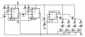
Here's the 556 timer suggestion: I used a D FF because discrete T FF can be finicky.
I breadboarded the circuit, but haven't tried the 180 second interval. There's a timing issue with the P MOSFETs because turn on is faster than turn off (I'm using a logic level device). I'm thinking about how to slow down the turn off on. After I do that, I'll get out a signal generator and counter to time the long interval.
Also haven't thought about power on reset for the timers. In my case, timer 1 was always triggering first, but that might not always be the case.
For some reason I thought you were designing your own board. If you are
you would have the PSOC chip + a driver chip on the board, a cap for
each chip. Maybe a regulator for chip supply if your supply unregulated.
Thats for a situation where you program chip before board placement.
Otherwise you would use a low end PSOC board and add another board.
You have to calculate for driver its dissipation to establish if it needs a heat
sink. Depends on the driver you pick. The one I referenced you should not
need a heat sink unless you are in a very hot environment. Using a PSOC
board programming it facility is on the board via USB.
I breadboarded the circuit, but haven't tried the 180 second interval. There's a timing issue with the P MOSFETs because turn on is faster than turn off (I'm using a logic level device). I'm thinking about how to slow down the turn off on. After I do that, I'll get out a signal generator and counter to time the long interval.
After spending some time trying to delay the falling edges to the gates of the P MOSFETs, I discovered that the D FF was behaving strangely (outputs stopped getting higher than 2V; I might have shorted the outputs too long). Swapped in a new CD4013, and the timing problem went away.
Set up a signal generator for a 1Hz square wave, set up a frequency counter, and went to make a couple female BNC to grabber adapters and my 40+ year old soldering iron decided to crap out. Now I need to look for some already made up.
Didn't see any problems with a 180 second interval for a 555 timer. Timed it for 10 cycles and it was off by a less than 1 second. Used a 220uF cap (calculated to be closer to 290uF) and around 550k for the resistance.
I let the signal generator and counter warm up for 4 or 5 hours before taking the measurements.
Something like this using ATTINY85, timing not as accurate as PSOC,
but low parts count. Use Bascom basic to write the code. I can post
PSOC project and you could translate that code into Bascom Basic
without much effort. ATTINY85 is 8 pin DIP. Regulator could always
be a zener and R in a shunt configuration. Although I have seen recently
that Chinese regs in the penny range. Not sure how good they are.
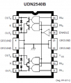
Google quad power driver, there are single chip driver solutions, some
even constant current. Versus using discrete MOSFETs.
One other comment, you might want to add a R to ground at each gate
of MOSFET to insure its held off while UP powering up. Most good UPs
power up with pins in tri state, so R insures LEDs are all off. Something
like 10K ohms.
Regards, Dana.
PS : Just caught the fact 2N7000 not rated for 350 mA, so use a logic
level part that will meet your specs, or a driver chip.
This is a little overkill as a driver, but worth considering. Eliminates
the discrete MOSFETs. Power wise might b e OK since only one
LED on at a time.
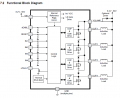
There's also a TI ULN2003 mosfet equivalent....TI TPL7407...see below.
I don't know...it may be overkill...it would get hot though at 350mA per channel without a heatsink.
The TS's circuit isn't gonna be all that compact if it needs heatsinks.

 Facebook
 Google
 GitHub
 Linkedin