Facebook
 Google
 GitHub
 Linkedin
Hello everyone!
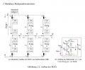
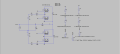
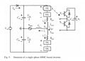
I am currently working with MMC and would like to simulate a half-bridge MMC (single-phase). Initially I just want to use one submodule per each arm. I have already completed the circuit. Problems:
Controlling the submodules
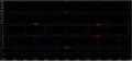
capacitor voltage balancing
can you please help me and thanks in advance
I am currently working with MMC and would like to simulate a half-bridge MMC (single-phase). Initially I just want to use one submodule per each arm. I have already completed the circuit. Problems:
Controlling the submodules
capacitor voltage balancing
can you please help me and thanks in advance
Attachments
-
 38.6 KB Views: 22
 -
3.3 KB Views: 16