Delay after power applied

Thread Starter

Justin Shands

Joined Aug 27, 2017
5
Hello all,

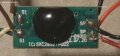
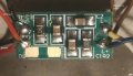
Here's the basic outline: I'm taking a circuit which previously had power constantly applied (it's a toy, which had batteries), and activated when the momentary switch was pressed (momentary switch isn't in-line from the power supply, it's a separate part of the circuit, connecting two pins on the circuit board). I am now attaching this to a power supply with it's own switch, which means I would like to have it activate as soon as power is applied. Holding the original switch down when the circuit is turned on doesn't work, it has to be released and then pressed again to activate it. I *believe* the proper way to resolve this is to create some sort of delay circuit so that when power is applied, there is a small delay before the original switch circuit is closed. (If someone has an alternate suggestion, I'd love to explore that as well.)

Basically:
Power on > short delay > switch circuit closed (remains closed until power off)

This is a 3v system, and I shouldn't need any long delays, it certainly feels like there should be a simple way to implement this without needing a 555 chip. I've briefly attempted to attach a capacitor to the switch circuit, but that does not seem to work. My next best guess is to do something with a transistor and a capacitor hooked to the V+ line from the power supply, so that when power is applied, the capacitor charges briefly, and then closes the switch circuit. Or possibly just a MOSFET by itself would provide enough delay?

I'm afraid I have only done incredibly simple circuits before, and trying to understand how this existing device is set up, and introduce new functionality to it is a bit beyond me.

I'm happy to take any additional readings, or I could attempt a circuit diagram if needed. I've attempted to search for other posts similar to this, and while I found many about delay circuits, they all seem to be more complicated than the delay I'm after (also, many of them just end without confirmation of success).
 

Externet

Joined Nov 29, 2005
2,223
Welcome, and welcome to digital gadgets which may have a microcontrolled switch to turn it on. The signal expected to turn it on needs a state change that afer power is removed, needs resetting and then is able to obey the momentary switch.
 

AnalogKid

Joined Aug 1, 2013
11,055
Let's see just how lucky you are. With all power removed, measure the resistance from each of the wires going to the switch to each of the wires going to the battery. If you are lucky, one of the wires will have a very low resistance (less than 1 ohm) to one of the power rails. If so, next apply power and then put a 10 ohm resistor across the open switch contacts. If this works, then a simple external R-C delay circuit and small MOSFET probably will work.

Also - it sounds lie the standard switch use is to push and let go. Power on the circuit and then apply a jumper across the switch to emulate holding the switch down continuously. If this does not cause problems, the circuit is simple. If this does cause problems and what you actually need is a delay, then a simulation of a momentary switch press, then things got a small bit more complex. In this case you will need active components, so an on-off pulse can be formed after the turn-on delay. A couple of transistors or one CMOS hex inverter.

ak
 

Thread Starter

Justin Shands

Joined Aug 27, 2017
5
Ok, one of the switch wires is tied directly to the power rail, and connecting the switch wires with a 10 ohm resistor does activate the circuit as though the switch were pressed.

I have attempted to a R-C circuit (attached, the rest of the circuit is still connected as it was previously, this portion simply connects to the 3v power and ground lines coming in) with a few different combinations of capacitor and resistor. I'm able to get it to come on by waiting to connect the Vc connection until after the power comes on, but if it's in place when power is switched on, it doesn't start working until I disconnect and reconnect it. I assume this is where the MOSFET would come in?

Do you have any advice for values I should be trying for resistor/capacitor/MOSFET for this configuration?

For the record, normal use is to hold down the button while you want the device activated, and release it when you want it to stop (my circuit will be changing this so it's "always on" whenever power is applied). Jumping the button connections does activate it as expected, as long as the button connection was open at some point after the power was turned on.
 

Attachments

ebeowulf17

Joined Aug 12, 2014
3,307
Ok, one of the switch wires is tied directly to the power rail, and connecting the switch wires with a 10 ohm resistor does activate the circuit as though the switch were pressed.

I have attempted to a R-C circuit (attached, the rest of the circuit is still connected as it was previously, this portion simply connects to the 3v power and ground lines coming in) with a few different combinations of capacitor and resistor. I'm able to get it to come on by waiting to connect the Vc connection until after the power comes on, but if it's in place when power is switched on, it doesn't start working until I disconnect and reconnect it. I assume this is where the MOSFET would come in?

Do you have any advice for values I should be trying for resistor/capacitor/MOSFET for this configuration?

For the record, normal use is to hold down the button while you want the device activated, and release it when you want it to stop (my circuit will be changing this so it's "always on" whenever power is applied). Jumping the button connections does activate it as expected, as long as the button connection was open at some point after the power was turned on.
I don't know if the simple RC circuit alone will work or not, but as long as you're trying it, I'd suggest adding a resistor from the "return path" side of the button to ground - something big, like maybe 10k. This will insure that the switch signal is low when it's supposed to be.

What resistance and capacitance did you try on your RC attempt? Maybe the timing is just too short - perhaps you need higher R and/or C values in order for the signal to stay low long enough.
 

Thread Starter

Justin Shands

Joined Aug 27, 2017
5
Ok, I added a 10k resistor between the return path and ground, the circuit seems to function the same as before. For the RC attempt, if I use any higher than 900 ohm resistor, the voltage is dropping too low to activate the circuit, and I've tried that in combination with a 55uF capacitor and it's not delaying the signal long enough to activate the circuit on power up if it's connected when the power is applied.

I suspect the issue might just be that my starting voltage isn't high enough to allow me to use a larger resistor and thus slow the signal down enough? Unfortunately the power source isn't really changeable, it's a 18650 battery built into a case (so it's actually 4v, not 3v when fully charged, but even fully charged it can't produce enough voltage through a 1k resistor to power the circuit).

Is starting so close to what I need for my final voltage (although I'm not sure what this value is, it operates at 2.9v when using the 1k resistor) akin to asking for "free" energy when attempting to use the inefficiency of certain components to slow down a signal?
 

ebeowulf17

Joined Aug 12, 2014
3,307
Ok, I added a 10k resistor between the return path and ground, the circuit seems to function the same as before. For the RC attempt, if I use any higher than 900 ohm resistor, the voltage is dropping too low to activate the circuit, and I've tried that in combination with a 55uF capacitor and it's not delaying the signal long enough to activate the circuit on power up if it's connected when the power is applied.

I suspect the issue might just be that my starting voltage isn't high enough to allow me to use a larger resistor and thus slow the signal down enough? Unfortunately the power source isn't really changeable, it's a 18650 battery built into a case (so it's actually 4v, not 3v when fully charged, but even fully charged it can't produce enough voltage through a 1k resistor to power the circuit).

Is starting so close to what I need for my final voltage (although I'm not sure what this value is, it operates at 2.9v when using the 1k resistor) akin to asking for "free" energy when attempting to use the inefficiency of certain components to slow down a signal?
Hmmm... I'm guessing the resistor I suggested adding to ground is working in conjunction with the RC resistor to create a voltage divider, and that's preventing operation above 900 ohms.
1) You might be able to eliminate my extra resistor to ground (I wasn't totally sure it was necessary, as it depends on unknown aspects of the rest of the circuit) and then continue trying higher resistor values in the RC circuit.
2) You might be able to just increase the ground resistor a lot (like 100k or 1Meg) and then continue trying higher RC values...
3) Or the most likely scenario is that you should trust the advice from @AnalogKid and see what MOSFET delay circuit he has in mind. His advice is always solid, whereas I'm a noob who tries to help when I can, but I still have a lot to learn.
 

Thread Starter

Justin Shands

Joined Aug 27, 2017
5
Hmmm... I'm guessing the resistor I suggested adding to ground is working in conjunction with the RC resistor to create a voltage divider, and that's preventing operation above 900 ohms.
1) You might be able to eliminate my extra resistor to ground (I wasn't totally sure it was necessary, as it depends on unknown aspects of the rest of the circuit) and then continue trying higher resistor values in the RC circuit.
2) You might be able to just increase the ground resistor a lot (like 100k or 1Meg) and then continue trying higher RC values...
3) Or the most likely scenario is that you should trust the advice from @AnalogKid and see what MOSFET delay circuit he has in mind. His advice is always solid, whereas I'm a noob who tries to help when I can, but I still have a lot to learn.
It seems like the added resistor was causing the issue, once I removed it, I was able to use higher resistor values, and once I got up to a 60k resistor with my 55uF capacitor, it does delay for long enough that the circuit now works with the button "closed" when the power is applied. I'll probably do some more toying around to see what the actual limits are (as well as ensure it continues to work at lower power as the battery drains), but I've at least got a working circuit now!

Thanks so much for everyone who helped me to figure this out!
 
Top