Decoding Chinese UART Protocol

Thread Starter

Rohan_jadhav

Joined Apr 6, 2023
14
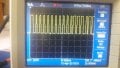
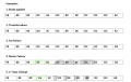
Hello Everyone, I am currently working on a EV project which has a Chinese UART based Protocol. which is used to transmit various data like speed, RPM, Errors etc to display. So aim is to decode this data, but i am unable to decode that protocol i have tried reading data from uart but garbage values are coming.... how to read this data?......1.png2.png3.png4.png1.png
 

Irving

Joined Jan 30, 2016
3,845
What exactly are you having trouble with? Resolving the '1's and '0's or making sense of the 8bit data? The '1's and '0's is a simple clocking/sync problem but you can't use a conventional UART as this isn't an RS232 mark/space protocol, you'll have to 'bit bang' it.
 

Ian Rogers

Joined Dec 12, 2012
1,136
Similar, but no master/slave addressing or r/w turn around, this is specifically one-way. Also the on/off ratio for bit timing in Dallas is typically 4:1 not 2:1 as here.
Agreed... But we both know its not UART.. This is a candidate for the CCP module.. The PCM seems to be pretty well consistent.
 

Papabravo

Joined Feb 24, 2006
21,159
It appears to be similar to the NEC IR protocol with the 38kHz carrier removed. It can easily be handled by an input capture module. The TS did not say if the protocol remains or attempts to remain synchronous over multiple bytes.
 

Irving

Joined Jan 30, 2016
3,845
It appears to be similar to the NEC IR protocol with the 38kHz carrier removed. It can easily be handled by an input capture module. The TS did not say if the protocol remains or attempts to remain synchronous over multiple bytes.
From the info it looks like it should remain synced over the 12 byte data transmission. If bit-banging using the first pulse to determine the length of the 96Tosc period (0.5 - 1mS) using a microseconds timer (+/- 4uS on a basic Arduino Uno) would give a count of 125 total or 42:83 (1) or 83:42 (0). That should easily remain synced over 96 bits. A faster MCU will have no difficulty.
 

Thread Starter

Rohan_jadhav

Joined Apr 6, 2023
14
What exactly are you having trouble with? Resolving the '1's and '0's or making sense of the 8bit data? The '1's and '0's is a simple clocking/sync problem but you can't use a conventional UART as this isn't an RS232 mark/space protocol, you'll have to 'bit bang' it.
I am developing an VCU which will upload data to cloud for that i need data passing through this line
 

Irving

Joined Jan 30, 2016
3,845
Something like:

Decoder:
#define inputPin 2

void setup() {
  // put your setup code here, to run once:
    Serial.begin(115200);
    pinMode(inputPin, INPUT);
}

void getData(byte* dataArray){
    byte data;
    byte *array = dataArray;
    noInterrupts();
    while(digitalRead(inputPin)==LOW); // wait for rising edge
    long t = micros();
    while(digitalRead(inputPin)==HIGH); // wait for falling edge
    int pwl = (int)(micros() - t)/2; // got pulsewidth
    for (int i = 0; i< 12; i++){
        data = 0;
        for(int j=0;j<8;j++) {
            delayMicroseconds(pwl);
            data |= digitalRead(inputPin) & 0x1; //sample data
            data <<= 1;
            while(digitalRead(inputPin)==LOW); // wait for rising edge (in case of 0)
            while(digitalRead(inputPin)==HIGH); //wait for falling edge
        }
        *array = data;
        array++;
    }
    interrupts();
}

byte myData[12];

void loop() {
  // put your main code here, to run repeatedly:
  getData(myData);
  Serial.print("Data = ");
  for(int b=0;b<12;b++){
        Serial.print(myData[b], HEX);
        Serial.print("  ";)
    }
  Serial.println();
  Serial.println();
}
 
Last edited:

Thread Starter

Rohan_jadhav

Joined Apr 6, 2023
14
What is a VCU? That doesn't really answer my question, but I'm guessing now its about capturing the 12 bytes of data not interpreting what they mean.
VCU means vehicle control unit which will uses to control as well as monitor EV parameters remotely... So my job is to decode data from this line and upload it to cloud....
 

Thread Starter

Rohan_jadhav

Joined Apr 6, 2023
14
I tried reading edges with arduino uno by using pulsein function but i am getting garbage data...

total time period of single logic is 3ms IF logic is '1' then the pulse will be low for 1ms and and high for 2ms and for logic '0' pulse will be low for 2ms and high for 1ms and between two frames there is delay of 34ms....


In excel sheet you can find the time delay in micro sec calculated by uno for high logic and low logic
 

Attachments

Thread Starter

Rohan_jadhav

Joined Apr 6, 2023
14
I tried reading edges with arduino uno by using pulsein function but i am getting garbage data...

total time period of single logic is 3ms IF logic is '1' then the pulse will be low for 1ms and and high for 2ms and for logic '0' pulse will be low for 2ms and high for 1ms and between two frames there is delay of 34ms....


In excel sheet you can find the time delay in micro sec calculated by uno for high logic and low logic

i have used following code


int pin = 7;
unsigned long duration_H = 0;
unsigned long duration_L = 0;

void setup() {
Serial.begin(9600);
pinMode(pin, INPUT);
}

void loop() {
duration_H = pulseIn(pin, HIGH);
duration_L = pulseIn(pin, LOW);
if (1500 <= duration_H && duration_H <= 2000) {
Serial.print("1");
} else if (1500 <= duration_L && duration_L <= 2000) {
Serial.print("0");
} else if (3200<=duration_L) {
Serial.println("NEXT DATA");
}
}
 

Irving

Joined Jan 30, 2016
3,845
i have used following code
I think your use of pulseIn() is flawed.

Arduino reference says:
" Reads a pulse (either HIGH or LOW) on a pin. For example, if value is HIGH, pulseIn() waits for the pin to go from LOW to HIGH, starts timing, then waits for the pin to go LOW and stops timing. Returns the length of the pulse in microseconds or gives up and returns 0 if no complete pulse was received within the timeout. "

If you look at the code for pulseIn() (below) you will see it waits for a previous pulse to finish - so your pulseIn(LOW) after a pulseIn(HIGH) waits for the pin to go HIGH again before looking for the LOW going edge... The inclusion of the Serial.print() statements could also throw things off further.... That why I prefer to code this directly (see post 10 above)

1680798964494.png


pulseIn:
/*
  wiring_pulse.c - pulseIn() function
  Part of Arduino - http://www.arduino.cc/

  Copyright (c) 2005-2006 David A. Mellis

  This library is free software; you can redistribute it and/or
  modify it under the terms of the GNU Lesser General Public
  License as published by the Free Software Foundation; either
  version 2.1 of the License, or (at your option) any later version.

  This library is distributed in the hope that it will be useful,
  but WITHOUT ANY WARRANTY; without even the implied warranty of
  MERCHANTABILITY or FITNESS FOR A PARTICULAR PURPOSE.  See the GNU
  Lesser General Public License for more details.

  You should have received a copy of the GNU Lesser General
  Public License along with this library; if not, write to the
  Free Software Foundation, Inc., 59 Temple Place, Suite 330,
  Boston, MA  02111-1307  USA

  $Id: wiring.c 248 2007-02-03 15:36:30Z mellis $
*/

#include "wiring_private.h"
#include "pins_arduino.h"

/* Measures the length (in microseconds) of a pulse on the pin; state is HIGH
 * or LOW, the type of pulse to measure.  Works on pulses from 2-3 microseconds
 * to 3 minutes in length, but must be called at least a few dozen microseconds
 * before the start of the pulse. */
unsigned long pulseIn(uint8_t pin, uint8_t state, unsigned long timeout)
{
    // cache the port and bit of the pin in order to speed up the
    // pulse width measuring loop and achieve finer resolution.  calling
    // digitalRead() instead yields much coarser resolution.
    uint8_t bit = digitalPinToBitMask(pin);
    uint8_t port = digitalPinToPort(pin);
    uint8_t stateMask = (state ? bit : 0);
    unsigned long width = 0; // keep initialization out of time critical area
    
    // convert the timeout from microseconds to a number of times through
    // the initial loop; it takes 16 clock cycles per iteration.
    unsigned long numloops = 0;
    unsigned long maxloops = microsecondsToClockCycles(timeout) / 16;
    
    // wait for any previous pulse to end
    while ((*portInputRegister(port) & bit) == stateMask)
        if (numloops++ == maxloops)
            return 0;
    
    // wait for the pulse to start
    while ((*portInputRegister(port) & bit) != stateMask)
        if (numloops++ == maxloops)
            return 0;
    
    // wait for the pulse to stop
    while ((*portInputRegister(port) & bit) == stateMask) {
        if (numloops++ == maxloops)
            return 0;
        width++;
    }

    // convert the reading to microseconds. The loop has been determined
    // to be 20 clock cycles long and have about 16 clocks between the edge
    // and the start of the loop. There will be some error introduced by
    // the interrupt handlers.
    return clockCyclesToMicroseconds(width * 21 + 16);
}
 

Thread Starter

Rohan_jadhav

Joined Apr 6, 2023
14
I think your use of pulseIn() is flawed.

Arduino reference says:
" Reads a pulse (either HIGH or LOW) on a pin. For example, if value is HIGH, pulseIn() waits for the pin to go from LOW to HIGH, starts timing, then waits for the pin to go LOW and stops timing. Returns the length of the pulse in microseconds or gives up and returns 0 if no complete pulse was received within the timeout. "

If you look at the code for pulseIn() (below) you will see it waits for a previous pulse to finish - so your pulseIn(LOW) after a pulseIn(HIGH) waits for the pin to go HIGH again before looking for the LOW going edge... The inclusion of the Serial.print() statements could also throw things off further.... That why I prefer to code this directly (see post 10 above)

View attachment 291583


pulseIn:
/*
  wiring_pulse.c - pulseIn() function
  Part of Arduino - http://www.arduino.cc/

  Copyright (c) 2005-2006 David A. Mellis

  This library is free software; you can redistribute it and/or
  modify it under the terms of the GNU Lesser General Public
  License as published by the Free Software Foundation; either
  version 2.1 of the License, or (at your option) any later version.

  This library is distributed in the hope that it will be useful,
  but WITHOUT ANY WARRANTY; without even the implied warranty of
  MERCHANTABILITY or FITNESS FOR A PARTICULAR PURPOSE.  See the GNU
  Lesser General Public License for more details.

  You should have received a copy of the GNU Lesser General
  Public License along with this library; if not, write to the
  Free Software Foundation, Inc., 59 Temple Place, Suite 330,
  Boston, MA  02111-1307  USA

  $Id: wiring.c 248 2007-02-03 15:36:30Z mellis $
*/

#include "wiring_private.h"
#include "pins_arduino.h"

/* Measures the length (in microseconds) of a pulse on the pin; state is HIGH
* or LOW, the type of pulse to measure.  Works on pulses from 2-3 microseconds
* to 3 minutes in length, but must be called at least a few dozen microseconds
* before the start of the pulse. */
unsigned long pulseIn(uint8_t pin, uint8_t state, unsigned long timeout)
{
    // cache the port and bit of the pin in order to speed up the
    // pulse width measuring loop and achieve finer resolution.  calling
    // digitalRead() instead yields much coarser resolution.
    uint8_t bit = digitalPinToBitMask(pin);
    uint8_t port = digitalPinToPort(pin);
    uint8_t stateMask = (state ? bit : 0);
    unsigned long width = 0; // keep initialization out of time critical area
   
    // convert the timeout from microseconds to a number of times through
    // the initial loop; it takes 16 clock cycles per iteration.
    unsigned long numloops = 0;
    unsigned long maxloops = microsecondsToClockCycles(timeout) / 16;
   
    // wait for any previous pulse to end
    while ((*portInputRegister(port) & bit) == stateMask)
        if (numloops++ == maxloops)
            return 0;
   
    // wait for the pulse to start
    while ((*portInputRegister(port) & bit) != stateMask)
        if (numloops++ == maxloops)
            return 0;
   
    // wait for the pulse to stop
    while ((*portInputRegister(port) & bit) == stateMask) {
        if (numloops++ == maxloops)
            return 0;
        width++;
    }

    // convert the reading to microseconds. The loop has been determined
    // to be 20 clock cycles long and have about 16 clocks between the edge
    // and the start of the loop. There will be some error introduced by
    // the interrupt handlers.
    return clockCyclesToMicroseconds(width * 21 + 16);
}
Sir I will try with your code... I agree with your statement of flaw. but as you can see that total time period is 3ms 1ms low and 2ms high for logic high, i was able to get time period nearby this you can see time period data attached above as time_delat.xlx.
 

Thread Starter

Rohan_jadhav

Joined Apr 6, 2023
14
Hmmm, OK. Do you have a 'scope? Can you capture the bitstream for a few examples and post them here?

I have manually capture 16 bits and converted to HEX they are using little endian order for sending data and i have got F8 80 for five sample as these two hex values are constant... S1-1 is first image, s1-2 is second image, s2-3 is third image and i have kept reference peak in each image check ripple in waveform.....
 

Attachments

Thread Starter

Rohan_jadhav

Joined Apr 6, 2023
14
I have manually capture 16 bits and converted to HEX they are using little endian order for sending data and i have got F8 80 for five sample as these two hex values are constant... S1-1 is first image, s1-2 is second image, s2-3 is third image and i have kept reference peak in each image check ripple in waveform.....
This is data taken from DSO with usb.....
 

Attachments

Top