Facebook
 Google
 GitHub
 Linkedin
Hi everyone,
Firstly, apologies if this is in the wrong forum - please move it if so.
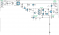
I'm trying to construct a power supply to run some brushed DC treadmill motors that I've collected, with which I plan to drive some power tools. They're all around 220 VDC at 1.5-2 HP. I've tried to understand the control circuits that came with the treadmills themselves, and have attached three different schematics (just the power circuitry, not the control side, which is largely painted over and resistant to analysis - I assume it's just PWM control in any case) that I've been able to more-or-less trace below. These diagrams are not complete (each circuit has a choke and an EMI filter on the input, and a small inductor on the leads close to the motor, for example), but I *think* they show the most important parts of the power electronics. Also, the "0R" resistors are all high-power (>5W) resistors that are too low for my sad little multimeter to measure, so all <0.1 ohm, and my local mains is 230V at 50Hz. Further, while I'm obviously not an expert, I've been trained in working with mains voltages and so forth, and feel comfortable in my ability to deal with the hazards here.
I think I understand the basic principles behind these controllers, but am not clear on a few points and would like to clarify them before trying to roll my own driver. The plan is to control speed with an MSP430 via an optocoupler, with a hall-effect sensor to feed back the motor speed.
So, questions:
1) I assume R4 (circuit 1) and R3 (circuit 2) serve as brake resistors to slow the motor when power is shut off. But what is the purpose of R3 and R2 (circuits 1 and 2, respectively)? Likewise, what is the purpose of R1 (also high power low resistance) in circuit 3?
2) In circuit 1, there is a capacitor across the rectifier, between AC and +ve - I've absolutely no idea what role it serves. There's also R1 from +ve to -ve (can't properly see the bands or measure its resistance) - is this likely just a bleed resistor for C3?
3) In circuits 1 and 2, the transistor is driving the motor from the high side; in circuit 3 it's driven low side. I've also seen other motor control circuits driving low side. Is there likely to be a particular reason for favouring one over the other?
4) The smoothing capacitors (C3, C1 and C1, respectively) all seem woefully inadequate for the current in question. Is this likely a case of "good enough" smoothing for a low-precision application, or might there be a reason for the values chosen?
5) What are C2 and R4 doing in circuit 2? Suppressing voltage spikes?
6) A more general question about these types of motors. When the motor says that it's rated for, say, 220V - is that likely to mean 220V peak or RMS? My assumption is RMS, but I've been unable to confirm that anywhere.
I think that's about all I needed to ask at this point. I'm starting to put together a schematic for my own power supply, drawing as best I can from these ones, and I'll incorporate anything that I can learn from people here, and hopefully post a schematic for feedback after that.
Thanks very much in advance for your help!
Firstly, apologies if this is in the wrong forum - please move it if so.
I'm trying to construct a power supply to run some brushed DC treadmill motors that I've collected, with which I plan to drive some power tools. They're all around 220 VDC at 1.5-2 HP. I've tried to understand the control circuits that came with the treadmills themselves, and have attached three different schematics (just the power circuitry, not the control side, which is largely painted over and resistant to analysis - I assume it's just PWM control in any case) that I've been able to more-or-less trace below. These diagrams are not complete (each circuit has a choke and an EMI filter on the input, and a small inductor on the leads close to the motor, for example), but I *think* they show the most important parts of the power electronics. Also, the "0R" resistors are all high-power (>5W) resistors that are too low for my sad little multimeter to measure, so all <0.1 ohm, and my local mains is 230V at 50Hz. Further, while I'm obviously not an expert, I've been trained in working with mains voltages and so forth, and feel comfortable in my ability to deal with the hazards here.
I think I understand the basic principles behind these controllers, but am not clear on a few points and would like to clarify them before trying to roll my own driver. The plan is to control speed with an MSP430 via an optocoupler, with a hall-effect sensor to feed back the motor speed.
So, questions:
1) I assume R4 (circuit 1) and R3 (circuit 2) serve as brake resistors to slow the motor when power is shut off. But what is the purpose of R3 and R2 (circuits 1 and 2, respectively)? Likewise, what is the purpose of R1 (also high power low resistance) in circuit 3?
2) In circuit 1, there is a capacitor across the rectifier, between AC and +ve - I've absolutely no idea what role it serves. There's also R1 from +ve to -ve (can't properly see the bands or measure its resistance) - is this likely just a bleed resistor for C3?
3) In circuits 1 and 2, the transistor is driving the motor from the high side; in circuit 3 it's driven low side. I've also seen other motor control circuits driving low side. Is there likely to be a particular reason for favouring one over the other?
4) The smoothing capacitors (C3, C1 and C1, respectively) all seem woefully inadequate for the current in question. Is this likely a case of "good enough" smoothing for a low-precision application, or might there be a reason for the values chosen?
5) What are C2 and R4 doing in circuit 2? Suppressing voltage spikes?
6) A more general question about these types of motors. When the motor says that it's rated for, say, 220V - is that likely to mean 220V peak or RMS? My assumption is RMS, but I've been unable to confirm that anywhere.
I think that's about all I needed to ask at this point. I'm starting to put together a schematic for my own power supply, drawing as best I can from these ones, and I'll incorporate anything that I can learn from people here, and hopefully post a schematic for feedback after that.
Thanks very much in advance for your help!
Attachments
-
164.7 KB Views: 134