I need to boost 100 mv dc voltage to 2.5 volt. In this circuit i am getting output same as input. May be its oscillator timing problem or Mosfet problem. Please help.
I can't really read the values on the schematic but:
looks like inductor is picohenries - far too low for what looks like 10 ms period
gate drive far too low - should swing from 0 V to at least 6 or 7 volts (haven't looked at datasheet, but it is an ancient FET so very unlikely to be logic level, and even if it were, gate drive of 1.6 V (again, can't read clearly) would be insufficient
Hi ebp
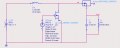
Sorry for bad picture. I got the MOSFET in ADS library. so could not get proper datasheet by the part number of ADS. Here i attach a new picture. For the booster, i need gate voltage less than 2.2 volt.
Even though you need low voltage for the gate for your actual circuit, try your simulation with 0 to 10 V for the gate.
Don't forget the basic equation δi/δt = V/L - differential of current in amperes with respect to time in seconds equals voltage across the inductor in volts divided by inductance in henries. With 9 ms of ON time with 0.1 V, δi of 1 ampere will require 900 µH.
Needing a FET that is ON at 2.2 volts will limit your choices, but you should be able to find some that are suitable as long as your current requirement is not large. I have no idea what may be available in the ADS libraries that would be suitable.
Without any description of why it does not do as expected, consider that the drive voltage is lower than the threshold voltage (Vth) which from the data sheet below is 1.7 volts. When switching a MOSFET the gate drive should exceed the threshold voltage by a substantial amount. www.farnell.com/datasheets/1911963.pdf
I increase the drive voltage up to 2.2 volts but yet now the same thing for 0.1-volt input I am getting 0.0045volt. Oscillator rise time is 9ms, fall time 1 ms. width 9.68ms. period 10ms.
The simulation output shown at #6 is a frequency response plot. That is not what is needed. You must do a time-domain (transient) plot so you can look at the voltages and currents versus time.
The circuit at #6 should work to some extent, but the FET still is not really suitable because it is not adequately turned on with 2.2 volts on the gate. At 100% efficiency you require an average current from the 100 mV input of 1.25 amperes to drive a 50 ohm load at 2.5 volts at the output (125 mW); the peak current will be higher and the FET used must have low drain-source voltage with 2.5 volts gate to source. The actual current will be higher still because efficiency is not going to be 100% (about 83% at best if you replace the silicon diode with a schottky diode).
Once again: try the original simulation with the inductor value changed and 0 V to 10 V of gate drive even if that is not what you will do with the real circuit.
As you can see, the capacitance used is much too small - the time constant is only a tenth of your period. It should be at about twice the period or more, so probably around 500 µF would be suitable. Of course this will mean it takes several switching cycles to get the voltage up to 2.5 volts. To determine the minimum value allowable you would need to consider the energy delivered from the inductor during the switch OFF time and the allowable output ripple voltage. If you allow more than a small amount of ripple it becomes more complex to analyze because you can't assume the inductor discharge current is linear (which is usually what is assumed - the capacitor voltage is almost constant during a single full switching cycle).
You are getting there. You can try reducing the gate drive voltage in the simulation to see what happens. I would do a binary search - go to 5 V, then to 7.5 or 2.5, depending on what 5 V shows you, and so on. But keep in mind the model probably has only typical values, and actual values can be considerably lower or higher and vary from one unit to another of the same type.
 Facebook
 Google
 GitHub
 Linkedin