 Facebook
 Google
 GitHub
 Linkedin
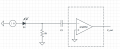
My goal is to amplify AC signal (~ nA) generated by a device resembling FET, where light changes the gate voltage, consequently changing the drain-source current. Here I drew it as a photodiode.
Drain-source bias voltage needs to be applied, which generates relatively large DC component (10 -100 uA) to the output.
The pre-amplifier (the box in the figure, don't ask what's inside) has very low noise characteristics and input impedance of 50 ohm. I am tempted to use it due to its good performance. However, the problem is this: the DC current exceeds the maximum input current (1 uA) for the amplifier. Thus, the circuit cannot be made as a simple transimpedance amplifier, where the detector would be directly connected to the amplifier input (virtual ground).
Blocking the DC component with capacitor would work, but in my circuit, the bias voltage of the detector is now divided between the resistor and the detector. Most likely, almost all the voltage would end up being over the resistor.
Is there any method of removing / reducing the DC component instead of using a different amplifier? Please note that the amplifier should be as near to the detector as possible to keep the noise level down.
Attachments
-
 17.2 KB Views: 22


