DC offset removal - precisely

Thread Starter

Aagash

Joined Jun 7, 2017
43
Hi,
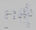
My signal is of frequency 0.8 - 1.3 Hz and 40mV (peak-peak) and has huge DC offset (+ve) . Is there a way to avoid DC offset and bring back to ref position .
If to use capacitor in series (will the signal at 0.8-1.3hz would remain uninterrupted ?) .
please suggest a way to acquire my signal . thanks in advance!
 

kubeek

Joined Sep 20, 2005
5,796
I think a better approach would be to pass that signal through an R-C low pass filter to obtain the average DC level, and then subtract this level from your signal with an operational amplifier. This approach would use much more managable values of the capacitor.
Does the DC level vary in time? Is it a known value, or is it dependant on external factors?
 

Thread Starter

Aagash

Joined Jun 7, 2017
43
I think a better approach would be to pass that signal through an R-C low pass filter to obtain the average DC level, and then subtract this level from your signal with an operational amplifier. This approach would use much more managable values of the capacitor.
Does the DC level vary in time? Is it a known value, or is it dependant on external factors?
Offset is fixed value , say around 4.5V . Could you show me with the rough schematic please !
 

crutschow

Joined Mar 14, 2008
38,389
I think a better approach would be to pass that signal through an R-C low pass filter to obtain the average DC level, and then subtract this level from your signal with an operational amplifier. This approach would use much more managable values of the capacitor.
I see no difference in the RC time-constant for either approach. :confused:

I vote for a simple blocking capacitor as recklessrog suggested.
It can be a polarized electrolytic, if you like. Just put the capacitor plus side towards the +ve offset.
For minimum attenuation, the capacitor with its load resistor should have a time-constant of at least 10 seconds.

Below is the LTspice simulation of a circuit with an RC value of 10 seconds.
As you can see in the bottom trace. the output compared to the input with the offset subtracted is virtually identical to the input.

upload_2017-8-14_16-36-9.png
 

Thread Starter

Aagash

Joined Jun 7, 2017
43
My
I see no difference in the RC time-constant for either approach. :confused:

I vote for a simple blocking capacitor as recklessrog suggested.
It can be a polarized electrolytic, if you like. Just put the capacitor plus side towards the +ve offset.
For minimum attenuation, the capacitor with its load resistor should have a time-constant of at least 10 seconds.

Below is the LTspice simulation of a circuit with an RC value of 10 seconds.
As you can see in the bottom trace. the output compared to the input with the offset subtracted is virtually identical to the input.

View attachment 132946
My output is from a filter circuit (active) , that is o/p from op-amp . is it still fine ? Do I just need to connect a capacitor and resistor in series and ground it ?
 

crutschow

Joined Mar 14, 2008
38,389
My output is from a filter circuit (active) , that is o/p from op-amp . is it still fine ? Do I just need to connect a capacitor and resistor in series and ground it ?
Yes, you connect a capacitor in series with the output followed by a resistor to ground.
 

MrAl

Joined Jun 17, 2014
13,680
My


My output is from a filter circuit (active) , that is o/p from op-amp . is it still fine ? Do I just need to connect a capacitor and resistor in series and ground it ?
Hi,

Oh ok, in that case you can also look into using a better op amp with low input offset as that may cure the problem. It depend where the offset originates though because if it comes from the input to that op amp then you have to deal with it accordingly, and sometimes you can just add a DC offset of opposite polarity which cancels the original offset but only if the original DC offset is very constant.

The things to watch out for using the capacitor coupling idea is the exponential time constant involved. If the DC offset changes, you could see a number of seconds before the offset goes back to exactly zero again. With a 1 second time constant it would take about five seconds, with a 10 second time constant it could take as long as 40 to 50 seconds. As usual, testing is a good idea.

Other more dynamic ideas include using a sample and hold circuit, but that requires the S&H circuit to be sync'd up to the input waveform which is not always possible.
 
Top