Facebook
 Google
 GitHub
 Linkedin
Hello there,
I signed up just to ask this as this seems like a pretty reactive group and knowledgable at that.
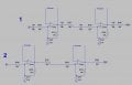
I'm designing and simulating a preamplifier that has multiple EQ's and different routing options, my issue is that im not entirely sure how DC offset is generated. Usually just following guidlines on Coupling Caps, etc would be okay but when all of these caps are added the signal gets very badly diminished in bandwidth. I've read about buffer amps but not entirely sure how that concept would work either. There are just too many stages between all of the EQ segments, specifically a cascaded series of parametric circuits to have caps inbetween each, can i just remove them? Does it matter when its so internal etc?
If possible can someone clearly explain either buffer amplifier circuits and how they remove DC offset or where DC offset is generated and how i could measure it either through simulation or testing?
I'd be very grateful, thanks to any that can help!
I signed up just to ask this as this seems like a pretty reactive group and knowledgable at that.
I'm designing and simulating a preamplifier that has multiple EQ's and different routing options, my issue is that im not entirely sure how DC offset is generated. Usually just following guidlines on Coupling Caps, etc would be okay but when all of these caps are added the signal gets very badly diminished in bandwidth. I've read about buffer amps but not entirely sure how that concept would work either. There are just too many stages between all of the EQ segments, specifically a cascaded series of parametric circuits to have caps inbetween each, can i just remove them? Does it matter when its so internal etc?
If possible can someone clearly explain either buffer amplifier circuits and how they remove DC offset or where DC offset is generated and how i could measure it either through simulation or testing?
I'd be very grateful, thanks to any that can help!