Facebook
 Google
 GitHub
 Linkedin
Hello Friends,
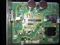
I have a treadmill that was bought many years ago. I do not have the pack of information that usually come with it when it is newly bought. Its motor controller went bust. I do not have circuit diagram for it. By doing some simple measurements, I found the driver transistor IRFP460A was blown up. I replaced it, the motor would work but there is no speed regulation, when the motor is heavily loaded this transistor will burn again. The speed feedback link is done using a reed magnetic relay., which I checked ok.
I am hoping that one of you may have the circuit diagram of this controller to do proper repair of this pcb. I attached a photo of this controller unit.
Kind Regards
Ayoob