DC motor rotation control using relays

Thread Starter

NikolaJP

Joined Nov 6, 2018
22
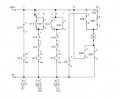
I have to make a circuit that has 3 buttons and uses relays to control the rotation direction of a dc motor.
One taster makes it rotate to the left, one to the right and the third makes the motor stop. I made a fluid sim simulation and my problem is that the motor short circuits when I want to switch directions, unless I stop it first.

DCControl.PNG
 

wayneh

Joined Sep 9, 2010
17,498
Do you really want instantaneous reversal of direction without stopping first? That put's a lot of mechanical stress on a motor and causes a current spike in the electronics, since the motor is essentially stalled and will draw maximum current.

And I see no mechanism to ensure that S1 and S2 switch together. Of course they will short if they are ever both "on".
 

Thread Starter

NikolaJP

Joined Nov 6, 2018
22
Do you really want instantaneous reversal of direction without stopping first? That put's a lot of mechanical stress on a motor and causes a current spike in the electronics, since the motor is essentially stalled and will draw maximum current.

And I see no mechanism to ensure that S1 and S2 switch together. Of course they will short if they are ever both "on".
How do I do te last part, to ensure they aren't both on?
That is my main problem since we won't connect this circuit, it only needs to work in theory.
 

wayneh

Joined Sep 9, 2010
17,498
How about a dual pole, single throw switch?

So there would be just two switches for the user, on/off and direction.
 

wayneh

Joined Sep 9, 2010
17,498
OK, well think about this: In your circuit, does the power switch S3 do anything useful when both S1 and S2 are "off"?

It's a clue to think about another use for S3.
 

wayneh

Joined Sep 9, 2010
17,498
OK, so it's occasionally redundant where it is now placed. Think about putting it somewhere else in the circuit where it is never redundant.
 

MaxHeadRoom

Joined Jul 18, 2013
28,686
One way of detecting low enough rpm in order to reverse is to wire a small relay across the motor, the hysteresis of a typical small 24vdc is a drop out of ~7vdc.
The relay could 'lock0out' each FWD REV switch until dropped out.
The motor BEMF will retain it until the 7v.
Failing that, a braking contact across the motor.
Max.
 

Thread Starter

NikolaJP

Joined Nov 6, 2018
22
One way of detecting low enough rpm in order to reverse is to wire a small relay across the motor, the hysteresis of a typical small 24vdc is a drop out of ~7vdc.
The relay could 'lock0out' each FWD REV switch until dropped out.
The motor BEMF will retain it until the 7v.
Failing that, a braking contact across the motor.
Max.
I have absolutely no clue how to do that.
 

Thread Starter

NikolaJP

Joined Nov 6, 2018
22
OK, so it's occasionally redundant where it is now placed. Think about putting it somewhere else in the circuit where it is never redundant.
I still couldn't think of anything. I would love trying to figure it out, but I have no time since I have to go to bed in an hour and go to school with the finished circuit early tomorrow morning.
 

wayneh

Joined Sep 9, 2010
17,498
For a given rotation direction you only need one switch, right? How about using S3 to switch between which of the other switches is in control? So you’d switch between forward/off and reverse/off.
 

Thread Starter

NikolaJP

Joined Nov 6, 2018
22
For a given rotation direction you only need one switch, right? How about using S3 to switch between which of the other switches is in control?
I need 3 buttons, S1-left, S2-right and S3-stop
I have to have these 3 buttons and their uses, It doesn't matter how many more switches I have in the circuit.
 

wayneh

Joined Sep 9, 2010
17,498
Are you saying you are required to have one switch dedicated to “all stop”? Perhaps you should share the exact requirements.
 

Thread Starter

NikolaJP

Joined Nov 6, 2018
22
Are you saying you are required to have one switch dedicated to “all stop”? Perhaps you should share the exact requirements.
Yes, those are the only requirements. Those three buttons and their functions, S1-left, S2-right and S3-stop.
 

wayneh

Joined Sep 9, 2010
17,498
Yes, those are the only requirements. Those three buttons and their functions, S1-left, S2-right and S3-stop.
Draw the truth table. You need to resolve what behavior you want when all three switches are “on”, since this the illogical short condition.
 

Thread Starter

NikolaJP

Joined Nov 6, 2018
22
Draw the truth table. You need to resolve what behavior you want when all three switches are “on”, since this the illogical short condition.
When all three buttons are on, I need the total to be off. I should probably make something like an XOR gate for the two direction buttons, but I don't know how to make that.
 

PhilTilson

Joined Nov 29, 2009
131
Hold on - are we missing the point here? The OP says that this is a theory problem, so the rapid reversal of the motor is irrelevant.

Referring to the original diagram, the problem, I would suggest, is that when S1 is pressed, K2 operates. The K2A contacts take the place of S1 when it is released, keeping the relay on. The K2B connects ground to the 'top' of the motor; K2C disconnects +24 from the top of the motor and K2D connects +24V to the bottom of the motor. So far, so good.

Pressing S3 operates K1. The K1A and K1B release K2 and K3 and the motor stops. Still so far, so good.

Now, let's go back to having pressed S1, so the motor is rotating one way. We now press S2, which operates K3. The K3A contacts short S2, thus keeping K3 on. K3B closes the path at the top of the motor, but since K2 is on, and K2C contacts are open, still no problem. But there is nothing to release relay K2!! So K2D takes +24V to the bottom of the motor AND through K3D direct to ground. Short circuit!

One easy (if somewhat untidy!) solution is to put a normally-closed set of K3 contacts (K3E) in the line between A1 and the K1A contacts, and a normally-closed set of K2 contacts (K2E) between A1 of K3 and the K1B contacts. Now, when S2 is pressed, K3 operates, K3E opens, releasing K2 so now power is fed via the normally-closed K2C contacts and K3B to the top of the motor and ground through the K3D contacts to the bottom of the motor, and it reverses direction. Once again, pressing S3 opens both relays so the motor stops.

Simples!
 

Attachments

Top