 Facebook
 Google
 GitHub
 Linkedin
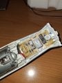
I would like to understand in detail what this circuit of an old kitchen mixer consists of.


On the left, just before the motor phases, there is a diode bridge and an RC filter, but I'm interested in figuring out what signal is input to the diode bridge, directly the AC input?
1. there are two red buttons, I can't tell if they are just buttons or there is something else inside, I usually see the tiny 4-pin buttons for use in breadboards, not as big as these in the picture.
2. the blue component has 3 pins and a small dissipator plate on top (can't be seen in the picture), what is it used for? Is it a transistor or a linear regulator?
3. the green resistor?
4. the purple one is an inductor? (it's MKP62 275 - X2 684K 40/110/56/B)
The diode bridge converts AC input to DC, so I exclude that the components just listed are part of a DC/DC converter.
Attachments
-
 1.5 MB Views: 3


