Circuit board troubleshooting - sewing machine motor control and power board

Thread Starter

scowex

Joined May 7, 2023
7
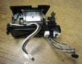
Hello - I have taken on a project helping a friend get her beloved Bernina (early 2000's?) sewing machine back up and running. The motor stopped running or turns slowly with the transformer humming. I also think the bobbin motor works off this board as well. I have attached a couple of files.
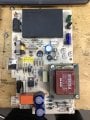
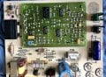
The motor runs on 110 VAC. The main transformer appears to have a split secondary. I checked all the capacitors with an ESR meter and they appear to be viable. The only one I could not check was C51 which is a 4700 Picofarad (it's value is outside of the test range of the meter). R17 was replaced - there were scorch marks on the board from a previous problem with it. I found the 200ma slo-blo fuse had high resistance and was partially blown. There appears to be an electrical path from that fuse, through the R17 resistor and into the mosfet 2SC23 (big heat sink). I am thinking that it may have shorted out at one point. I have also checked for cold joints and other artifacts on the board. The foot rheostat appears to work (no dead spots) and the connectors appear sound to the board. Unfortunately there is no schematic available.

Obviously I am lost here...It would be nice to understand how the board works and why it's so complicated. I don't think the stitch patterns are generated from it. On the older boards, there was a motor run or start capacitor that went out frequently and was fairly obvious.
 

Attachments

MaxHeadRoom

Joined Jul 18, 2013
30,557
Those later M/C's often had a BLDC motor and controller, so may be a little harder to diagnose,
No sign of any Stressed components ??
 

Thread Starter

scowex

Joined May 7, 2023
7
Those later M/C's often had a BLDC motor and controller, so may be a little harder to diagnose,
No sign of any Stressed components ??
The motor is labeled '110 VAC' motor, so it is not a BLDC. I have combed the discrete component side of the board for cold solder joints, signs of distress,etc. as well as testing the capacitors with my ESR meter (all good). The only clues I have so far is a 220 ohm resistor that had blown and left scorch marks (previously replaced). This resistor pins have board continuity to a 200 ma slo-blow fuse which is partially blown (high resistance) and a power mosfet in a heat sink. The other clue is that the motor tries to start and won't - the transformer hums instead. If there is a start/run capacitor it may be on the motor assy which I have not taken off yet. There is a mystery 4700 picofarad cap near the transformer that I can not test in situ. As I said all the other board caps check out. Unfortunately, there is no schematic. I have started one for it but it is nowhere near complete. I think my next step is to replace the fuse and observe, and if that fails, start testing the mosfets starting with the one traced to the resistor and fuse. Then take the motor out and look for the start run caps. In this case, ignorance is not bliss ;-)
 

MaxHeadRoom

Joined Jul 18, 2013
30,557
One simple test to find out if it is AC induction or PM field motor, is to short all three motor stator leads and try and spin by hand, the PM version will exhibit a series of 'bumps' each time it crosses a pole.
With induction, there is no difference.
 

Thread Starter

scowex

Joined May 7, 2023
7
One simple test to find out if it is AC induction or PM field motor, is to short all three motor stator leads and try and spin by hand, the PM version will exhibit a series of 'bumps' each time it crosses a pole.
With induction, there is no difference.
I don’t want to remove the motor quite yet, but there is no magnetism on the case/core. Attached are some photos of a similar motor. There
are wires that I surmise generate the magnetic field when energized.
 

Attachments

Thread Starter

scowex

Joined May 7, 2023
7
Hi,
first of all, check the motor. It is a 110VAC motor, so it's quite easy to check it
I understand about checking the simplest first…and certainly checking the motor qualifies as a smart check rather than making an assumption that the problem is elsewhere. Early on, I did get the motor to run briefly and was able to control the rpm.

I am not sure the motor is that easy to check … it may not be as simple as simple as putting 110 vac to the brush leads.
I am not sure, but I think the motor’s speed is controlled by
varying the voltage to the stator coils and I have no idea what that requirement is.

Historically, the motors are not a common point of failure. Brushes do wear out though and that is good check to make.

I was thinking about putting another 200 Ma fuse in, powering up and checking the board for hot spots with a thermal camera.

Thank you
 

MaxHeadRoom

Joined Jul 18, 2013
30,557
I don’t want to remove the motor quite yet, but there is no magnetism on the case/core.
With a modern BLDC motor etc, the PM magnetics are all in the rotor.
If the motor has brushes and runs on AC supply, then it is a Universal motor. (Series connected, AC/DC).
It has the appearance of a Universal version.
 

Pyrex

Joined Feb 16, 2022
501
With a modern BLDC motor etc, the PM magnetics are all in the rotor.
If the motor has brushes and runs on AC supply, then it is a Universal motor. (Series connected, AC/DC).
It has the appearance of a Universal version.
Seems like that.
But , i see three wires on the photo. Usually those motors use two wires:confused:
 

Thread Starter

scowex

Joined May 7, 2023
7
One simple test to find out if it is AC induction or PM field motor, is to short all three motor stator leads and try and spin by hand, the PM version will exhibit a series of 'bumps' each time it crosses a pole.
With induction, there is no difference.
Thanks MHR and everyone who responded for your help - I finally received the fuse replacements. I had previously found a fuse that looked good, but after checking it with a VOM, it turned out to be partially blown (high R). So ... replaced it and for now, all seems okay and working for now. It was an old board with a previous repair, so who knows. Although there is no board schematic to be found, I did find the manual with road maps of what each part of the board and fuses pertained to and a rudimentary flow chart.
 
Top