Dc-Dc conveter

Thread Starter

AymanKhuzundar

Joined Apr 2, 2017
61
Hi every one;
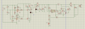
I have attached a schematic for a Dc-Dc boost converter ; the left side is working as a window comparator while the right side is the main circuit used to boost the voltage from 12v up to 24v
when I tried the Dc-Dc circuit, it worked very well , but when connect it to the window comparator and increase the voltage slowly the relay switches on-off very fast , I've tried the window comparator without connecting it with the boost circuit and it worked
what is the problem ? shall I use another driver instead of the relay ??
Thanks all
 

Attachments

AlbertHall

Joined Jun 4, 2014
12,346
You have no decoupling capacitors on the window comparator supply. Try a 100uF and also 100nF capacitors across U2 supply and ground pins using the shortest wires possible.
 

dendad

Joined Feb 20, 2016
4,472
One thing that jumps out is the lack of bypass capacitors.
Try adding a 100nF cap acronym D7 and another and a 10uF tantalum across the power pins on U2 for a start. You need to make sure the power supply is clean and has a relatively low impeadance to noise.
Other than that, I'm assuming the circuit design works.
Ah, I see AlbertHall beat me to it ;)
 

AlbertHall

Joined Jun 4, 2014
12,346
Even then, there might be a problem as the relay connects a (probably discharged) 100uF across the supply when its contacts make.
You might need to separate the supply to the comparator with a diode.
All the supply connections for the comparator would be connected by a diode to the battery positive with the decoupling capacitors as previously described around the comparator. Now, when/if the battery supply spikes downwards the diode isolates the comparator from that spike.
 

Thread Starter

AymanKhuzundar

Joined Apr 2, 2017
61
as I understood I have to add two capacitors at the supply of the U2 , and separate U2 from the battery by a diode , but the problem hasn't been solved :((
I've also tried to remove the capacitors C1 and C2 but that didn't solve the problem
I haven't tried these solutions practically , would there be a difference between practical and simulation ?
thanks all
 

Thread Starter

AymanKhuzundar

Joined Apr 2, 2017
61
One thing that jumps out is the lack of bypass capacitors.
Try adding a 100nF cap acronym D7 and another and a 10uF tantalum across the power pins on U2 for a start. You need to make sure the power supply is clean and has a relatively low impeadance to noise.
Other than that, I'm assuming the circuit design works.
Ah, I see AlbertHall beat me to it ;)
sorry but what do you mean by (acronym D7)? shall I replace it by another component ? I use it as a regulator of 5v
 

dendad

Joined Feb 20, 2016
4,472
sorry but what do you mean by (acronym D7)? shall I replace it by another component ? I use it as a regulator of 5v
Ah!
My iPad auto correct strikes again!
That should read "across"
One day I will find out how to turn it off.

edit... My Dear Wife just fixed it for me:)
 

Thread Starter

AymanKhuzundar

Joined Apr 2, 2017
61
Ah!
My iPad auto correct strikes again!
That should read "across"
One day I will find out how to turn it off.

edit... My Dear Wife just fixed it for me:)
wish GOD bless you :) :)

nothing changed :(
the problem happens when the relay is about to connect , I'm looking at the Vin of the comparator and see that it's changing unexpectedly
 

dendad

Joined Feb 20, 2016
4,472
You may need to increase the hysteresis of the comparators to over come the supply drop when the relay operates.
Another thing to try is to feed R12 and R17 from a decoupled sample of the battery. Add an extra 1K resistor in series from the battery to R12/R17 then put a 100uF cap from that point to 0V.
Have you tested the comparators to measure the turn on/turn off voltages?
A real measurement to test what hysteresis you have could be of interest.
 

Dodgydave

Joined Jun 22, 2012
11,301
R19 is connected to the Inverting pin (-)instead of the Non-inverting pin (+), also don't know why you're using two transistors to put the relay on, use one transistor and use diodes from each ic output to turn the transistor on/off.
 

Thread Starter

AymanKhuzundar

Joined Apr 2, 2017
61
R19 is connected to the Inverting pin (-)instead of the Non-inverting pin (+), also don't know why you're using two transistors to put the relay on, use one transistor and use diodes from each ic output to turn the transistor on/off.
it's an (and) gate , there is another schematic for window comparator but I prefer this type :)
 
Top