DC/DC Converter Transformer model Analysis

Thread Starter

mike _Jacobs

Joined Jun 9, 2021
223
I dont really expect anyone to answer this since its fairly in depth but ill post it anyway.

I am trying to follow this example in a book
Equation 3.24 i was able to derive.

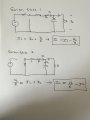
You must write two KVL equations for VL with the ideal switch in position 1 and position 2.
Then you do the integral and that falls out.... ok fine...

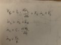
Where i am lost is equation 3.25. As you can see, the book does not proof anything for it and i cant figure out how they got here.

To even get started you have to be able to write a KCL equation for the capacitor in both switch one and switch 2 positions.
I am struggling to do that correctly. I have tried it several ways but cant get the correct answer.

If anyone knows how to write the KCL for the capacitor in the two different switch states i should be able to take it from there.

Thanks in advance.


1714250971772.png
 

Thread Starter

mike _Jacobs

Joined Jun 9, 2021
223
iL=iC+iR
iL = iC + Vc/R

In ideal capacitor all current flowing into is equal current flowing out, so average capacitor current is zero.

then iL=0+Vc/R
Could you please tell me which switch state you are saying is for each of your KCL's

I have done the math as you suggested and it does not line up with the books proof.
The only way the books answer is correct is if KCL is the same for both switch states which obviously cant be true.

The only way it works is if

Ic = IL-VC/R for both switch states. If this is not so then the book is wrong. so it must be
 

Thread Starter

mike _Jacobs

Joined Jun 9, 2021
223
The way I have done the KCL has to be wrong since it does not match the book.

It can be seen below that my attempt to proof this equation has failed.
I can make it work as the book does but not with two KCL equations that make any kind of sense to me.
I will post the way i can make it work but you will see that the KCL makes no sense.

The only way the proof works and matches the book is if the KCL is the same for both states aka both equation 1 and equation 2
Where Equation 1: IC = IL - VC/R and Equation 2: IC = IL = VC/R


1714258754327.jpeg1714259343543.jpeg
 

Attachments

Last edited:

Thread Starter

mike _Jacobs

Joined Jun 9, 2021
223
Here is how I can make the proof work
But as you can see, equation 1 must = equation 2 which makes. I sense from a KCL perspective

1714260026643.jpeg
.
1714260152194.pngFrom Book
 

Thread Starter

mike _Jacobs

Joined Jun 9, 2021
223
The assumption about average capacitor current =0 is valid for whole period T. Because during Ton the current flows to capacitor and during Toff outside to R.
That makes sense when you look at the answer of the equation being set equal to zero.
What you are describing is the reason the final answer is set equal to zero.
1714261424301.png

I am still unable to complete the proof.

It simply does not work algebraically
 
Last edited:

Thread Starter

mike _Jacobs

Joined Jun 9, 2021
223
When iL decreases under iR the capacitor starts supply R also (not only inductor), i.e. the current flows outside the capacitor.
If that’s the case the KCL equation has to be something different
I don’t understand because a second ago you agreed that the KCL equation is the same for both states but in your last post
You say the current changes directions and the cap discharges. (Which makes sense)
But if it changes directions KCL can’t possibly be the same for both states
 

Thread Starter

mike _Jacobs

Joined Jun 9, 2021
223
Just in case someone stumbles upon this thread 10 years from now i might have come up with an explanation for this proof.
If you look at the waveform of the inductor current it actually changes polarity 4 times made evident by the 4 arrows i marked.

I believe the cause of this is because of then current leading the voltage in a capacitor. So the current actually changes polarity 90 degrees after the switching event.

That would mean there are actually 4 KCL equations to represent the two states of the main switch being closed and main switch being open.

The current is out of phase with the switching event and therefore does not change direction exactly in line with the switch as made evident by the attached photo.

1714322479067.png


So if that is true, then there are 4 KCL Equations and i believe if you could actually write them out correctly you would find some of them cancel out with each other. Giving what appears to be two equations of the same polarity which would make the proof work.
 
The differential equation-s (their nature) describing circuit make this current direction changes you mention by itself, since they are able to differentiate positive and negative currents also (automatically).

One variable is iL and one vC.


So you need two diff. equations for two states (4 equations overall ) only.
 
Last edited:
Top