DC-AC inverter, Full H-Br use of two spwm signals only (without 50 hz pwm)

Thread Starter

vik93

Joined Dec 29, 2024
11
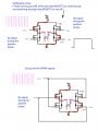
SgtWookie wrote: I mean turning just ONE of the low-side MOSFETs on continuously, and switching the high-side MOSFET on and off for PWM. You might have problems trying to keep a high-side MOSFET on continuously.
---

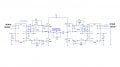
I noticed, that Egs002 module has 4 outputs (from IR2110). Two SPWM signals go to the H-Br, 2HO and 1HO, the other two -> 50 hz pwm go to low side mosfets (2LO and 1LO).

Question
Why 4 outputs? The SPWM is modulated by 50 hz signal (positive and negative sine wave). It has the 50 hz information. As SgtWookie said, it might be some problems if one mosfet stays on for a long time, while the other one switches on and off.
Can I use from the Egs002 two outputs only?
 

ronsimpson

Joined Oct 7, 2019
4,646
I think the bottom two FETs switch at 50 or 60hz. 50% on, out of phase.
I think the top two FETs switch at 24khz. PWM

Gate drive for top FET and other side bottom FET.
1735781679197.png
 

Thread Starter

vik93

Joined Dec 29, 2024
11
Thank you for the quick answer Ronsimpson.
The question is: why do we need the 50hz pwm signals to Low Mosfets if all information already inside (the modulated by 50hz) 24kHz SPWM signal? Why to keep the 2LO and 1LO on for a long time (is it 0.02s?)
I used the LtSpice with using only SPWM signals and it works.
 

Attachments

ronsimpson

Joined Oct 7, 2019
4,646
For 1/2 the 50hz time, Bottom Left FET is on and Top Right FET is PWM. Red
For the other 1/2 cycle, Bottom Right FET is on and Top Left FET is PWM. Green
1735791366060.png
Waveform across the transformer.
1735791949249.png
 

Ian0

Joined Aug 7, 2020
13,097
Question
Why 4 outputs? The SPWM is modulated by 50 hz signal (positive and negative sine wave). It has the 50 hz information. As SgtWookie said, it might be some problems if one mosfet stays on for a long time, while the other one switches on and off.
Can I use from the Egs002 two outputs only?
Yes, you can make a half-bridge instead of a H-bridge, but you will need two power supplies, one positive and one negative.

If you have a H-bridge, you need three possible states, and that requires four output transistors to achieve.
 

MisterBill2

Joined Jan 23, 2018
27,164
The inverter in this discussion is a form of a switching mode power supply. My recent answer to a previous question still holds: It is a very complex task, exactly as the explanations from R.S. show!!
 

Thread Starter

vik93

Joined Dec 29, 2024
11
Ronsimpson said: You will have AC losses on both FETs, not just on the top side.
--------------------

Is it in the case of controlling the h-bridge with 4 signals or 2?
 

nsaspook

Joined Aug 27, 2009
16,250
Ronsimpson said: You will have AC losses on both FETs, not just on the top side.
--------------------

Is it in the case of controlling the h-bridge with 4 signals or 2?
https://www.tntech.edu/engineering/pdf/cesr/ojo/asuri/Chapter2.pdf

SPWM With Bipolar Switching
SPWM With Unipolar Switching
SPWM With Modified Bipolar Switching Scheme

https://www.etasr.com/index.php/ETASR/article/view/7150/3676
This paper provides a comparative analysis of bipolar versus unipolar Sinusoidal Pulse Width Modulation (SPWM) in DC-AC inverters, focusing on Total Harmonic Distortion (THD) across modulation indices and the latter’s effects on the R-L loads. Using the PIC18F2431 microcontroller for its efficiency, a single-phase inverter accomplished to deliver a high-fidelity sine wave. This study discovered that while both SPWM methods reduce harmonics, the unipolar approach yields more uniform THD reduction and superior performance, particularly noticeable in RL load conditions, where minimal harmonic distortion is crucial. The bipolar inverter, despite a higher initial THD, shows a considerable improvement at higher indices, significantly enhanced by an LC low-pass filter. This filter is a key component in achieving sub-1% THD levels at full modulation, ensuring optimal sine wave quality. The findings highlight the operational differences between the SPWM techniques and the importance of the LC filters in ameliorating the inverter output for various power applications.
 
Last edited:

nsaspook

Joined Aug 27, 2009
16,250
Hi nsaspook
Thank you for the pdf and direction.
Glad to be of help. My baseline PIC32MK SPWM board can be configured for just about any PWM mode.

Here, it's setup for two-phase servo motor 400Hz power generation using bipolar SPWM.
1735872983072.png

No filter on the H-bridge outputs.
1735873024909.png
The FFT shows the 400Hz content of the PWM signals.

1735873054078.png
Carrier H-bridge outputs with 400Hz modulation and o-scope math for the bipolar output result across the bridge.
https://forum.allaboutcircuits.com/...drature-phase-400hz-motor.187708/post-1746642

400Hz filter outputs.
https://forum.allaboutcircuits.com/...r-for-3-phase-115v-supply.181424/post-1666364

Board details.
https://forum.allaboutcircuits.com/threads/pic32mk-mc-qei-example.150351/post-1538575
1735873502843.png
Older 1.2 version board schematic https://github.com/nsaspook/vcan/blob/qdrive_14_board/pic32mks.pdf
H-Bridge driver and output chip: https://github.com/nsaspook/vcan/blob/qdrive_14_board/MC33932.pdf
1735874630035.png
 
Last edited:

Thread Starter

vik93

Joined Dec 29, 2024
11
Understood nsaspook.
I study the 12v DC to 240vAC inverter work.
Plan to use the IR2110 (x2) drivers, but not in unipolar (as the Egs002 does), but in bipolar switching mode. I found that bipolar H-Br control offer a very good voltage regulation. Not sure, how good it is.
Timer1 used in Nano (in mode 8): 10kHz carrier is modulated by 50hz sine wave. The Chapter2.pdf directed me to some more info on internet. Need to read more later.
 
Top