 Facebook
 Google
 GitHub
 Linkedin
I came across a set of Gerber files and a partial BOM for this meter, and I could use some help in filling in some blanks.
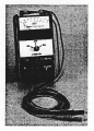
This was a signal strength meter used with a system where you could transmit a carrier wave over an electric distribution system to send instrument readings or remotely control loads.
The BOM I had appeared to be cut off, omitting four components; that's one of the questions I had (educated guesses as to the missing values of the components). C15 (on the first stage - feedback path on U10), R41 (in the second stage, after the filter), and R56 / D5 (LT1017 op-amp circuit).
The other questions I had have to do with the schematic -
What type of meter movement would have been attached to M1? Ammeter or voltmeter?
The 555 seems to be some kind of boost circuit to bump the 9V battery current to a higher voltage, correct? Would it be fair to assume it would be 12V?
What is the function of the LT1017 circuit?
Attachments
-
 252 KB Views: 15
 -
285 KB Views: 26


