Facebook
 Google
 GitHub
 Linkedin
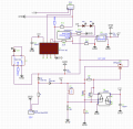
hi,The power source is a standard 12v 7Ah feeder battery. The voltage will typically fluctuate between 13+v and 11.5+v. The unit works just fine down to 10v.
AS the circuit has no regulator for the 12V supply, consider using two Schottky diodes for reverse voltage protection.
E
Added: example type PDF

Attachments
-
301.1 KB Views: 2
Last edited: