D Flip Flop Struggles

Thread Starter

robin105

Joined Mar 7, 2015
3
Hi,

I'm having quite a difficult time getting this d flip flop to work! It's starting to drive me insane.

The part I'm using is "74HC374 74374 OCTAL D-TYPE FLIP-FLOP IC", the data sheet is here:
http://www.taydaelectronics.com/datasheets/A-1148.pdf

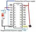
And below I've attached a image that shows how I connected the wires. Also the power supply is 5V.

As you can see, I connected the input of one of the D flip flops to the power supply, to indicate a high voltage, and I was hoping, when I would press the button for the clock, the input from the "1D" terminal would now be the output in my "1Q" terminal.

But it just doesn't work... The LED never lights up (the LED is connected from 1Q to ground, and yes the LED works).

Any suggestions...?
 

Attachments

Papabravo

Joined Feb 24, 2006
21,225
The HC part should be able to light a grounded LED assuming you take ericgibbs' advice. The TTL part will not be able to source enough current to light a grounded LED. However if you connect the Q output of the Flip-flop to the LED cathode, and the LED anode to the 470R resistor to the supply it will happily sink the required current.

In the datasheet look at the difference in the parameters "I_sub_ol" and "I_sub_oh". These currents are for the output low (ol) and output high (oh). Notice how symetrical the HC part is and how asymmetrical the plain old TTL part is. Every engineer I have ever known in a career spanning half a century has been tripped up by the difference.
 

Roderick Young

Joined Feb 22, 2015
408
Other tips if it still doesn't work: 74HC parts don't assume a 0 or 1 on unconnected inputs. You should probably have a 100k or so resistor (doesn't really matter, 1k to 1 meg would work) going from the clock pin to ground to keep it at 0. When you push the button, the Vcc will bring the clock pin to 1.

Another tip is that mechanical pushbuttons exhibit this thing called contact bounce. When you push the button, the contacts actually go on-off-on-off...on for a few milliseconds. It doesn't matter for what you're doing whether you get one or fifty clock pulses, but it could in some later circuit.

In theory, leaving any inputs open puts them in an uncertain state, and may result in excess power dissipation. Ideally, you would tie the unused D and OE inputs to ground.
 

WBahn

Joined Mar 31, 2012
30,058
To summarize the myriad problems you have:

1) Your LED needs to have a series current limiting resistor, otherwise even if it works will stress the part.

2) You need to debounce your clock signal (though you can the circuit working, albeit erratically, without that).

3) You need to enable your outputs by grounding the \OE pin.

4) You need to apply known logic levels to ALL unused input pins.

5) You need a pulldown resistor on the clock pin so that you actually have a clock signals. As it is, you take the clock pin from HI to UNKNOWN and back as you cycle the switch.
 

Thread Starter

robin105

Joined Mar 7, 2015
3
Thank you so much ericgibbs, Papabravo, Roderick Young, and WBahn, it works perfectly! And from reading all the replies, I have a much deeper understand!
 

DickCappels

Joined Aug 21, 2008
10,172
In future digital logic projects/experiments it would be good to add good high frequency decoulping between the Vcc and Ground pins. A .01 ceramic in parallel with 10 uF or more would do.
 
Top