 Facebook
 Google
 GitHub
 Linkedin
Hello all,
I'm tasked with building a boost converter with the following:
I realize that to do CV, I need to control the duty cycle as the input voltage and the load changes. I have only ever designed something similar to this in MATLAB, which is very abstracted from the nitty gritty of circuit design.
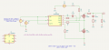
How would I go about designing this converter? I've got my basic converter attached here.
I've also attached a TI report on current mode boost converters, which is a bit daunting to me. Would I be better served with a programmable IC? If so, which would you recommend?
I'm tasked with building a boost converter with the following:
- 3-4V in
- 12V out
- 9A max input current
I realize that to do CV, I need to control the duty cycle as the input voltage and the load changes. I have only ever designed something similar to this in MATLAB, which is very abstracted from the nitty gritty of circuit design.
How would I go about designing this converter? I've got my basic converter attached here.
I've also attached a TI report on current mode boost converters, which is a bit daunting to me. Would I be better served with a programmable IC? If so, which would you recommend?
Attachments
-
 29.3 KB Views: 9
 -
557.1 KB Views: 6


