Cutoff frequency of LC filter

Thread Starter

omar-rodriguez

Joined Jun 24, 2015
67
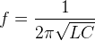
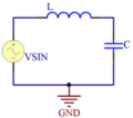
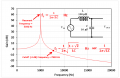
Hi I was trying to find the cutoff frequency of an LC low pass filter, you know
The first I did was to find the transfer function with the impedance divider in the 's' domain:


Then I found the magnitude of the function transfer when s=jw


Then I found w when the amplitude reaches -3.01dB=1/sqrt(2)
so:


Finally I got:
But it suppose to be
???
 

Attachments

Last edited:

shteii01

Joined Feb 19, 2010
4,644
Take the maximum amplitude. Multiply it by 0.707, this is your amplitude at the cutoff frequency. Plug it into the formula and solve for omega.
 

WBahn

Joined Mar 31, 2012
30,060
Where are you getting that it is supposed to be 1/(2π√(LC))?

Is it possible you are confusing cutoff frequency with some other type of frequency?
 

Thread Starter

omar-rodriguez

Joined Jun 24, 2015
67
Everyone knows that the cutoff frequency of the LC low pass filter is 1/(2*pi*sqrt(L*C)), but I don't get this expression this is why I made the question
 

MrAl

Joined Jun 17, 2014
11,486
Hi,

I think what we have here is a marvelous example of why simulators alone are not always enough so without real hard and fast theoretical circuit analysis we could easily come to the wrong conclusion that there might be something like a -3db point.

In pure theory, this is not really a filter circuit and there is no solution. Outside of pure theory, there is not enough information given to correctly find the answer. Note that simulators seem to provide a solution but they are always introducing parasitic elements either electrically or numerically and either on purpose or just by way of the way they compute things.

In short, exciting a purely resonant circuit with it's exact resonant frequency leads to an infinite response, and an infinite response has no -3db point.

In order to remedy the situation, we have to introduce some loss element somewhere, and that can come in the form of a series resistor and/or load resistor. Then we have something to compute. Until then, this circuit lies in another one of those novelty realms in the land of pure theory.

Take note that you can never find a -3db point without some loss somewhere in this circuit.
 

Papabravo

Joined Feb 24, 2006
21,225
Going back to your transfer function, you get resonance when the denominator vanishes. From:

\(LC\omega^2\;-\;1\;=\;0\)
\(\omega^2\;=\;\frac{1}{LC}\)
\(\omega\;=\;\frac{1}{\sqrt{LC}}\)
\(f\;=\;\frac{1}{2\pi\sqrt{LC}}\)

The other way to derive this is to understand that resonance occurs when

\(X_L\;=\;X_C\)
\(\omega L\; =\;\frac{1}{\omega C}\)
\(LC\omega^2\;=\;1\)

Also -- it doesn't matter if the reactances are in series or in parallel. they still pass energy back and forth.
 
Last edited:

MrAl

Joined Jun 17, 2014
11,486
Going back to your transfer function, you get resonance when the denominator vanishes. From:

\(LC\omega^2\;-\;1\;=\;0\)
\(\omega^2\;=\;\frac{1}{LC}\)
\(\omega\;=\;\frac{1}{\sqrt{LC}}\)
\(f\;=\;\frac{1}{2\pi\sqrt{LC}}\)

The other way to derive this is to understand that resonance occurs when

\(X_L\;=\;X_C\)
\(\omega L\; =\;\frac{1}{\omega C}\)
\(LC\omega^2\;=\;1\)

Also -- it doesn't matter if the reactances are in series or in parallel. they still pass energy back and forth.
Hi,

I was also wondering if this should even be called resonance. This is one of those circuits that is so far from reality that we need special assumptions to be able to define anything exactly.

For example, at "resonance' the current would be infinite. Does that swamp the source or no? If we allow the source to handle infinite current then the peak output is at infinity, so infinite current, infinite output amplitude.

What do you think?

BTW for the previous posts here, the (if present) -3db point(s) is (are) not at the point(s) where the response falls 3db from the w=0 point, it's where the response falls 3db from the maximum output unless there are special circumstances and then it could be the point where it falls 3db from some other reference point, where that reference point is deemed pertinent to the application.

What we should probably do here is insert some resistance (even 0.01 ohms) somewhere and then recalculate. If this is really supposed to be a filter, maybe just a load resistor then. For example with RL=100 and L=C=1 we get approximately w=1.005 and w=0.995 as the two -3db points.
 
Last edited:

Papabravo

Joined Feb 24, 2006
21,225
Hi,

I was also wondering if this should even be called resonance. This is one of those circuits that is so far from reality that we need special assumptions to be able to define anything exactly.

For example, at "resonance' the current would be infinite. Does that swamp the source or no? If we allow the source to handle infinite current then the peak output is at infinity, so infinite current, infinite output amplitude.

What do you think?

BTW for the previous posts here, the (if present) -3db point(s) is (are) not at the point(s) where the response falls 3db from the w=0 point, it's where the response falls 3db from the maximum output unless there are special circumstances and then it could be the point where it falls 3db from some other reference point, where that reference point is deemed pertinent to the application.

What we should probably do here is insert some resistance (even 0.01 ohms) somewhere and then recalculate. If this is really supposed to be a filter, maybe just a load resistor then. For example with RL=100 and L=C=1 we get approximately w=1.005 and w=0.995 as the two -3db points.
You can wonder all you like about what something should be called. Can you convince others to come around to your viewpoint? Possibly. I see nothing wrong with your analysis or the points you have raised. Series and parallel resonant circuits have been around for a long time and that is how they are referred to. Resonance occurs when the response is enhanced at a particular frequency. Certainly as the resistance approaches zero in the limit the response becomes unbounded. We deal with limits and singularities all the time, and I don't understand your problem with them.
 

Thread Starter

omar-rodriguez

Joined Jun 24, 2015
67
Going back to your transfer function, you get resonance when the denominator vanishes. From:

\(LC\omega^2\;-\;1\;=\;0\)
\(\omega^2\;=\;\frac{1}{LC}\)
\(\omega\;=\;\frac{1}{\sqrt{LC}}\)
\(f\;=\;\frac{1}{2\pi\sqrt{LC}}\)

The other way to derive this is to understand that resonance occurs when

\(X_L\;=\;X_C\)
\(\omega L\; =\;\frac{1}{\omega C}\)
\(LC\omega^2\;=\;1\)

Also -- it doesn't matter if the reactances are in series or in parallel. they still pass energy back and forth.
mmm.... I think that I was confusing resonant frequency with cutoff frequency thanks
 

MrAl

Joined Jun 17, 2014
11,486
You can wonder all you like about what something should be called. Can you convince others to come around to your viewpoint? Possibly. I see nothing wrong with your analysis or the points you have raised. Series and parallel resonant circuits have been around for a long time and that is how they are referred to. Resonance occurs when the response is enhanced at a particular frequency. Certainly as the resistance approaches zero in the limit the response becomes unbounded. We deal with limits and singularities all the time, and I don't understand your problem with them.
Hello again,

Not that big of a problem. In pure theory i think we have to accept it as resonance. In reality, it can never be a real circuit. Much of the other stuff we deal with can appear in a real circuit. Pure philosophy deals with what is real and what is not real.
https://en.wikipedia.org/wiki/Reality
 

MrAl

Joined Jun 17, 2014
11,486
mmm.... I think that I was confusing resonant frequency with cutoff frequency thanks
You should not get hung up on this circuit though. A real circuit like this WILL have one or two -3db points.
Add a load resistor, then calculate again to see the difference. Any real circuit will have some resistance.
 

MrAl

Joined Jun 17, 2014
11,486
Except, that these circuits are used in all sorts of RF devices, despite their limitations.
Hi again,

I've never seen a circuit in real life that has an ideal voltage source, ideal capacitor, and ideal inductor in it, and what is more is that those are being the ONLY components in the circuit.

As i said, add a resistor somewhere though and all this clears up right away and then acts more like a circuit we may actually encounter somewhere in the real world.

This is not the first time a discussion like this has come up in history and it comes up in electrical theory because of the unworldly responses. Another area that has been argued about is the existence of an impulse. We use the impulse response of a circuit like butter on bread, but there are those that would argue against it.

I dont feel that this deserves any more attention however and that is because i can see you are not interested in these kinds of discussions, not everyone wants to talk about ideas of existence and non existence. These kinds of talks are at the edge of reality, where the human mind find's it's limitations and somehow automatic approximations of what is real in order to be able to deal with life. If you are not into that kind of thinking then you are probably not open to understanding the implications and so this kind of discussion will never do you any good.
 
mmm.... I think that I was confusing resonant frequency with cutoff frequency thanks
Hi,
I have the same question as you actually. Thanks for your post.
I think it is not your fault.
The problem is 'Everyone knows that the cutoff frequency of the LC low pass filter is 1/(2*pi*sqrt(L*C))' while in reality, it should be resonant frequency rather than cutoff frequency. Calling it as cutoff frequency is incorrect but a lot of people are still doing that.
 
Hello! My first post. I came up with the exact same equation as omar-rodriguez for the -3 dB cutoff frequency for an LC circuit. And like Omar, I am amazed that so many people are assuming the equation 1/(2π sqrt(LC)) is the -3 dB cutoff frequency. That's wrong! That equation is for the resonant frequency, not the -3 dB cutoff frequency. Even DigiKey gets it wrong.

https://www.digikey.com/en/resource...sion-calculator-low-pass-and-high-pass-filter

Slide1.PNG
Slide2.PNG


Plot.png
 

Attachments

Top