Cut off video signal then amplify

Thread Starter

Milika Delic

Joined Jun 25, 2018
10
Hello,
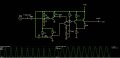
I have been torturing myself with this problem and finally decided to ask for help :)

I want to take Y Componen video signal, cut syncs off and amplify it for my adc.
So...
Cut 0-0.7v
Amplify 0.7-1.4v -> 0-3.3v

I would like to do it with npn transistors only...

Any help is most appreciated :)

Regards
 
There are many NPN transistors available that you can use to amplify the signal. However, it mainly depends on the nature of your project. Before you intend to pick the right transistor, you must check the ratings of the transistors and check if they resonate with your project.

Based on your requirement, I'd suggest you check 2n3903 transistor.
 

danadak

Joined Mar 10, 2018
4,057
Not trivial what you are asking using discrete transistors.

Google "video sync stripper" to see whats involved.

Regards, Dana.
 

DickCappels

Joined Aug 21, 2008
10,180
In the 1970's and 1980's I used to do this sort of thing a lot. This circuit should not be difficult to design or find on the web provided we know what it needs to do.

What power supplies are available?

This would probably be a lot easier if PNP's are allowed. Can you accept a PNP or two?

Are you ok with using an integrated circuit amplifier to amplify the signal?

Are you going to use this in conjunction with the color difference signals? (If the answer is "no" then things will be a little easier.)

Is your video signal already clamped to a given DC level? If so, to what level is it clamped.

Is a detected sync pulse or back porch clamp pulse available?

Once clamped the sync can be clipped off reliably.

From what type of video is the Y signal derived (NTSC, PAL, SECAM)? <==This has to to with bandwidth requiremnts

What is the amplitude of the video envelope and what is the full scale input to your ADC?
 

Thread Starter

Milika Delic

Joined Jun 25, 2018
10
Wow, great question, this forum is great.

It is a PAL signal, PNP or NPN are ok, ICs I would love to avoid. Especially op amps, i had severe stock problems with them in the past,
I have 2.5v, 3.3v and 5v available, perhaps 1.2v all regulated.

This is a Pure Y (luminance) + Sync signla from S-Video standard.
I already made sync detector, so it can be used, its simple but it would nicely. It gives Sync clock to 3.3v.

Video signal is at 0.7v IRE, meaning it fluctuates between ~0.4v and ~1.4v.

ADC is cutom made and can do 16bit at 3.3v theoretically, but 12bit is more realistic.
I would need 6bit at least usable.

Thank You all for great replies!!!
 

DickCappels

Joined Aug 21, 2008
10,180
You may want to start with this. R13 and R14 are only there to make a 700 mv video signal for simulation purposes.Further, I would add a resistor in series with D1and vary the current through it so that you can have a fine adjustment of offset. Or similar to what MrChips indicated, you can perform the offset adjustment in software.

upload_2018-6-27_0-13-44.png
 

Thread Starter

Milika Delic

Joined Jun 25, 2018
10
Wow, great work, im going to start on it emediatly. I think i have all the parts.
Will get back soon.

Removing sync in digital sacrifices 33% of precision, thats the only reason.
 

Thread Starter

Milika Delic

Joined Jun 25, 2018
10
Ok I quickly recreated the circuit in this little online app, its usually pretty good, but now cant seen to make the circuit work.

Probably I do not understand it, its way above my head :)

Here is the screenshot and link to so you can see the circuit in action
http://tinyurl.com/yb6cggh5

Most likely my inputs are of completely... But cant seem to figure it out....
 

Attachments

DickCappels

Joined Aug 21, 2008
10,180
Your simulation looks good except that because I did not explain the circuit you did not know that the input to the 1 nf capacitor that feeds the lower transistor (the one with 4.7k on the base and collector) is supposed to be the 3.3V sync pulse.

The power supply is 5.0 volts.

The sync pulse needs to be synchronous with the video, so plugging in a 40 Hz sine wave will result in kind of a mess because the clamp expects to see the same level every 64 microseconds.

For the purposes of simulation I took the sync signal and divided that down to make a synchronized 700 mv pulse to simulate an a 700 mv video signal that happens to be white during the sync time.

The positive-going sync pulse is applied to C1.
The 700 mv Y signal is applied to C2.

In the circuit Q3 in conjunction with R3 and C1 make a back porch clamp pulse from your sync pulse, Q1 is a unity gain buffer, followed by Q2 which is the active clamp in conjunction with C3, while Q4 and Q5 form a non-inverting amplifier with gain to bring the 700 mv signal up to about 3.3V.

The voltage on the collector (acting as emitter) of Q2 that is more than one base-emitter drop from ground is the DC offset of the signal going into the amplifier. You will need to adjust this voltage to accommodate the pedestal and component variations.

I hope your ADC has a pretty high input impedance because there is no negative power supply, and I am a bit concerned about slew rate of the signal close to ground. A negative supply may be needed for R10.

I have attached the LTSpice simulation file. Download link for Mac and Windows 7, 8, and 10:
http://www.analog.com/en/design-center/design-tools-and-calculators/ltspice-simulator.html
 

Attachments

Thread Starter

Milika Delic

Joined Jun 25, 2018
10
Wow, great circuit, it will amplify about 65us after the sync pulse. I see, completely different approach from my amateur one. Great!

Thank you!!
 

DickCappels

Joined Aug 21, 2008
10,180
You are most welcome.

Let us know if you run into problems with the real life circuit. My experience with those who digitize is that there is always one more little detail that pops up. That happens with video amplifiers too.
 

Thread Starter

Milika Delic

Joined Jun 25, 2018
10
Will do, now digging out npn/pnp suitable trans from my piles :)

Output is going to my, already in use, sigma delta comparator with FPGA module.

Thank You again!
 
Top