 Facebook
 Google
 GitHub
 Linkedin
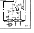
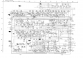
I want to do a component video mod on a Sony PVM-1220. I can inject Y into the composite video port and Pb and Pr into the RGB matrix board at connector BA-6. The service manual lists both voltages as 0.5vpp but they are actually 0.5vpp (b-y) and 0.4vpp (r-y) and this as at MAX contrast. if I lower the contrast then the Y signal decreases but my Pr and Pb would remain at the same level and that'll cause the colors to be wrong. How do I fix this?
One option would be amplify Pb and Pr and then use an adjustable pot to change the voltages manually. This should work but I'd have to add an extra knob to the set and manually change if I change contrast. Is there any way to build a circuit that would force Pr and Pb to follow Y, so decrease Pr and Pb as Y decreases? This is outside my technical experience.
One option would be amplify Pb and Pr and then use an adjustable pot to change the voltages manually. This should work but I'd have to add an extra knob to the set and manually change if I change contrast. Is there any way to build a circuit that would force Pr and Pb to follow Y, so decrease Pr and Pb as Y decreases? This is outside my technical experience.
Attachments
-
 22.8 KB Views: 7
 -
 999.5 KB Views: 9


